


Appendix A: Technical Specifications
128
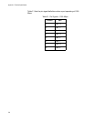
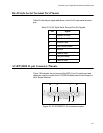
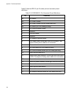
Table 23 lists the RPS 21-pin D-combo port and connector pinout
definitions.
Table 23. AT-RPS3000 21-Pin Connector Pinout Definitions
Pin Definition
A1 12V Return
A2 12V Power Contact
A3 56V Power Contact (for PoE Ready port only)
A4 56V Return (for PoE Ready port only)
1 12V Positive Remote Sense
2 Reserved
3 RPS3000 Status
4 Reserved
5 12V Negative Remote Sense
6 RPS Power Good. Active high, from RPS to switch. This
signal is floa
ting when cable is not connected.
7 Reserved
8 56V Load Share (for PoE Ready port only)
9 56V Positive Remote Sense (for PoE Ready port only)
10 Tied to ground inside RPS
11 Switch power good indication. Active high input from switch
to RPS. This sign
al is floating when cable is not connected.
12 Reserved
13 Extra PoE power available. Active high, from RPS to switch.
14 Reserved
15 Tied to ground inside switch
16 Reserved
17 56V Negative Remote Sense (for PoE Ready port only)