


x610 Series Layer 3 Gigabit Ethernet Switches Installation Guide
61
The Physical
Stack
Depending on the switch types used, a stack can comprise from 2 to 8
individual stack members interconnected via high speed stacking links. A
stack always has a primary stack member called the stack master, and
can contain up to 7 other stack members. For information about VCStack
stacking modules available and cable specifications, see “Connecting
switches into a stack” on page 67 for more information.
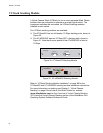
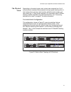
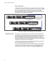
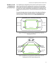
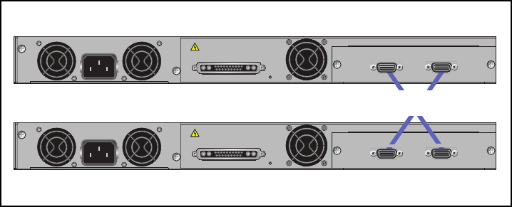
Two Switch Stack Configuration
This configuration, shown in Figure 33, uses two switches that are
connected back to back via two high-spee
d stacking links. In this
configuration the stack can still function using only a single high speed
link. Note that stacking ports labeled 1 must connect to stacking ports
labeled 2. Also, in this example the switches have AT-StackXG stacking
modules installed.
POWER SUPPLY
RPS
READY
RPS INPUT
12V/21A MAX
STACKING
WARNING
This unit may have more than one power input. To reduce the risk of
electric shock, disconnect both A/C and RPS inputs before servicing
unit.
100-240VAC~
AT-StackXG
STACK PORT 1
STACK PORT 2
POWER SUPPLY
RPS
READY
RPS INPUT
12V/21A MAX
STACKING
WARNING
This unit may have more than one power input. To reduce the risk of
electric shock, disconnect both A/C and RPS inputs before servicing
unit.
100-240VAC~
AT-StackXG
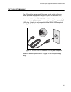
High Speed Stacking Cables (0.5 meter)
Model Number AT-StackXG/0.5
STACK PORT 2
STACK PORT 1
Figure 33. Back-to-Back Topology (x610 Switches)