


x610 Series Layer 3 Gigabit Ethernet Switches Installation Guide
43
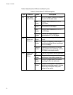
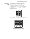
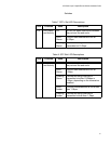
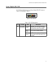
Table 9. System STATUS LED Descriptions
LED State Description
FAULT Off Indicates normal operation.
Red
Flashing
The switch or management software is
malfunctioning. This LED lights and then turns off
after hardware initializes. The following flash
sequences indicate a hardware-related fault.
After sequences of two or more flashes, the LED
stops briefly, then repeats the sequence. If
multiple faults occur, the LED flashes each
sequence in turn, stops briefly, then repeats the
sequences.
1 Flash This state is not supported on the x610 Switches.
2 Flashes One or more than one of the chassis fan rotors or
the pluggable POE chassis power supply fans is
operating below the recommended speed.
3 Flashes This state indicates a chassis power supply fault
and the chassis is powered by AT-RPS3000
Redundant Power Supply. This indication applies
to all non-POE and POE models.
4 Flashes This state is not supported on the x610 Switches.
5 Flashes The RPS3000 is connected to the x610 switch,
but no RPS power is available to be supplied.
6 Flashes The switch’s temperature has exceeded the
recommended threshold.
MASTER Off Indicates that the switch is not the Stack Master.
Flashing
Green
Indicates the specific stack member’s ID of the
switch in response to the ‘show stack indicator’
command. The LED will repeatedly flash ‘n’ times
in quick succession, followed by a longer pause,
where n is the stack member's ID.
Solid
Green
Indicates that the switch is the Stack Master.
RPS Off No optional redundant power supply is
connected to the switch.
Solid
Green
An optional redundant power supply is physically
connected to the switch and may be powered on
or off.