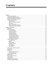
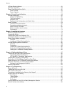
Contents
6
VCStack Stacking Module..........................................................................................................................54
AC Power Connector..................................................................................................................................55
Power Over Ethernet Plus (PoE+)..............................................................................................................56
Power Classes .....................................................................................................................................56
Power Capacity....................................................................................................................................57
Chapter 2: Virtual Chassis Stacking ............................................................................................................59
VCStack Introduction..................................................................................................................................60
Features of VCStacking .......................................................................................................................60
The Physical Stack...............................................................................................................................61
Resiliency Link .....................................................................................................................................62
Resiliency Link Configurations via Switch Ports ..................................................................................63
Stack Formation .........................................................................................................................................64
The Role of the Stack Master...............................................................................................................64
Connecting switches into a stack.........................................................................................................67
Steps to set up a VCStack ...................................................................................................................69
Steps to replace a stack member.........................................................................................................71
Provisioning..........................................................................................................................................71
Chapter 3: Installing the Hardware ...............................................................................................................73
Reviewing Safety Precautions....................................................................................................................74
Unpacking a Switch....................................................................................................................................77
Installing the Power Cord Retaining Clip....................................................................................................78
Installing the Switches in an Equipment Rack............................................................................................79
Power Supply Module Installation ..............................................................................................................81
Overview ..............................................................................................................................................81
Installing a VCStack Stacking Module .................................................................................................82
VCStack Stacking Module Installation........................................................................................................88
Overview ..............................................................................................................................................88
Preparation...........................................................................................................................................89
Installing a VCStack Stacking Module .................................................................................................89
Cabling an AT-StackXG Stacking Module ...........................................................................................93
Cabling an AT-x6EM/XS2 Stacking Module.........................................................................................94
Chapter 4: Cabling the Network Ports .........................................................................................................97
Twisted Pair and Fiber Optic Specifications...............................................................................................98
Twisted Pair Cable Specifications........................................................................................................98
SFP and SFP+ Transceiver Specifications..........................................................................................99
Installing SFP and SFP+ Transceivers.....................................................................................................100
Cabling the 10/100/1000Base-T and Fiber Optic Ports............................................................................102
Power Wiring to a DC AT-PWR250 Power Supply Module......................................................................103
AC Power Connection to a Power Supply Module ...................................................................................107
Starting a Local Management Session ..............................................................................................109
Warranty Registration...............................................................................................................................110
Chapter 5: Troubleshooting ........................................................................................................................111
Power LED is Off......................................................................................................................................112
Twisted Pair Port Link LED is Off .............................................................................................................113
SFP or SFP+ LED is Off...........................................................................................................................114
Transceiver is Installed but the Status is “Not Present”............................................................................115
System Fault LED is Flashing ..................................................................................................................116
Two Flashes.......................................................................................................................................116
Three Flashes ....................................................................................................................................116
Five Flashes.......................................................................................................................................116
Six Flashes.........................................................................................................................................116
Cannot Establish a Local (Out-of-Band) Management Session...............................................................117
Switch Functions Intermittently.................................................................................................................118


