


x610 Series Layer 3 Gigabit Ethernet Switches Installation Guide
63
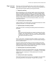
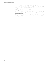
Resiliency Link
Configurations
via Switch Ports
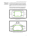
Two resiliency-link configurations that connect to switch ports are shown
below. Figure 35 shows the resiliency link connecting in a ring topology,
whilst Figure 36 shows the resiliency link connectin
g to its switch ports via
a network hub. In both configurations,
the resiliency link connections are
made using the ResiliencyLink VLAN and attaching the switch ports to the
VLAN.
For more information about the stack resiliency link refer to the Stacking
Intr
oduction and Stacking Commands chapters in the AlliedWare Plus
Operating System Software Reference from www.alliedtelesis.com.
x610-24Ts
x610-24Ts
x610-24Ts
x610-24Ts
Stacking Links
Connecting to Switch PortsStack Resiliency Link -
ResiliencyLink VLAN
x610-24Ts
x610-24Ts
x610-24Ts
Network Hub
x610-24Ts
Stacking Links
Resiliency Links
to Switch Ports
Figure 35. Resiliency link Connecting to Switch Ports Over the
ResiliencyLink VLAN
Figure 36. Resiliency link Connecting to sWitch Ports Over the
Resilie
ncyLink VLAN Using a Network Hub