


x610 Series Layer 3 Gigabit Ethernet Switches Installation Guide
81
Power Supply Module Installation
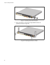
Overview The x610-24Ts-POE+, x610-24Ts/X-POE+, x610-48Ts-POE+ and
x610-48Ts/X-POE+ switches are supplied with
a factory installed blank
panel on the power supply slot. Either an AC or DC version of the 250W
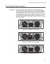
(AT-PWR250) power supply shown in Figure 43 and Figure 44, 800W
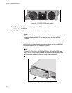
(AT-PWR800) power supply, shown in Figure 45 on page 81, or a 1200W
(AT-PWR1200) power supply, shown in Figure 46 on page 82, can be
installed in these switches. The installation pro
cedure is identical for each
type of power supply.
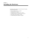
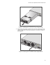
100-240VAC~ 5A MAX
DC PWR
FAULT
AT-PWR250
2196
2197
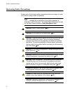
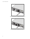
FOR CENTRALIZED DC POWER
CONNECTION, INSTALL ONLY IN A
RESTRICTED AREA.
40-60VDC
6A
OUTPUT POWER
FAULT
AT-PWR250
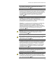
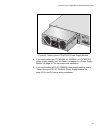
100-240VAC~ 12A MAX
DC PWR
FAULT
AT-PWR800
Figure 43. AT-PWR250 AC Power Supply
Figure 44. AT-PWR250 DC Power Supply
Figure 45. AT-PWR800 Power Supply