


Chapter 3: Installing the Hardware
78
Installing the Power Cord Retaining Clip
This section applies to the fixed power supplies installed in the x610-24Ts,
x610-24Ts/X, x610-48Ts, and x610-48Ts/X switches and to the
AT-PWR250 and AT-PWR800 power supply modules.
Note
The AT-PWR1200 power supply does not have a retaining clip.
Perform the following procedure to install the power cord retaining clip on
the switches:
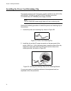
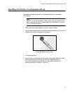
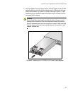
1. Locate the power cord retaining clip, shown in Figure 38.
100-240VAC
~
Figure 38. Power Cord Retaining Clip
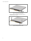
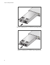
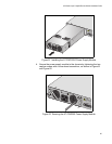
2. Install the clip on the AC power connector on the rear panel of the
switch. With the ‘u’ of the clip facing down, press the sides of the clip
toward the center and insert the short ends into the holes in the
retaining bracket, as shown in Figure 39.
Figure 39. Inserting the Retaining Clip into the Retaining Bracket
You are now ready to install the switches in the equipment rack, as
explain
ed in the next procedure.