


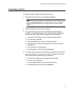

100-240VAC~ 16A MAX
DC PWR
FAULT
AT-PWR1200
2267
Chapter 3: Installing the Hardware
82
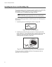
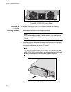
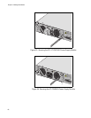
Figure 46. AT-PWR1200 Power Supply
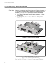
Installing a
VCStack
Stacking Module
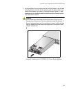
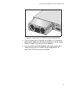
To install a power supply into a POE chassis, perform the following
procedure:
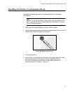
1. Remove the module from the shipping package.
2330
POWER SUPPLY
RPS I
56V/18A MAX
WARNING
This unit may have more
electric shock, disconne
unit.
AT-LX44CPUCVR
Note
Store the packaging material in a safe location. You must use the
original shipping material if you need to return the unit to Allied
Telesis.
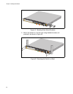
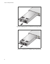
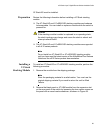
2. Remove the blank panel from the power supply slot on the rear panel
of the switch by loosening the two captive screws on the panel with a
cross-head screwdriver, as shown in Figure 47.
Note
The x610-24Ts-POE+, x610-24Ts/X-POE+, x610-48Ts-POE+ and
x610-48Ts/X-POE+ switch chassis are shipped from the factory with
a blank panel installed in the rear panel power supply slot.
Figure 47. Removing the Blank Panel from the Power Supply Slot