


x610 Series Layer 3 Gigabit Ethernet Switches Installation Guide
29
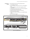
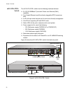
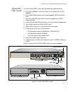
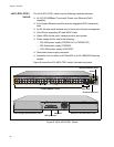
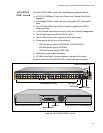
x610-48Ts/X-
POE+ Switch
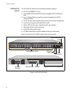
The x610-48Ts/X-POE+ switch has the following hardware features:
48 10/100/1000Base-T ports with Power over Ethernet Plus (PoE+)
capability.
Two Gigabit Ethernet small form-factor pluggable (SFP) transceiver
slots
Two 10 Gigabit Ethernet small form-factor pluggable plus (SFP+)
transceiver slots
An RJ-45 style serial terminal port for local (out-of-band) management
One SD slot supporting SD and SDHC cards
Status LEDs for the ports, transceiver slots, and system
Power supply slot for one of the following:
– 250 Watt power supply (PWR250-AC or PWR250-DC)
–
800 Watt power supply (PWR800)
– 1200 Watt power supply (PWR1200)
Redundant power supply connector
AT-LBM (Loop Back) module installed in the rear of the switch
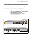
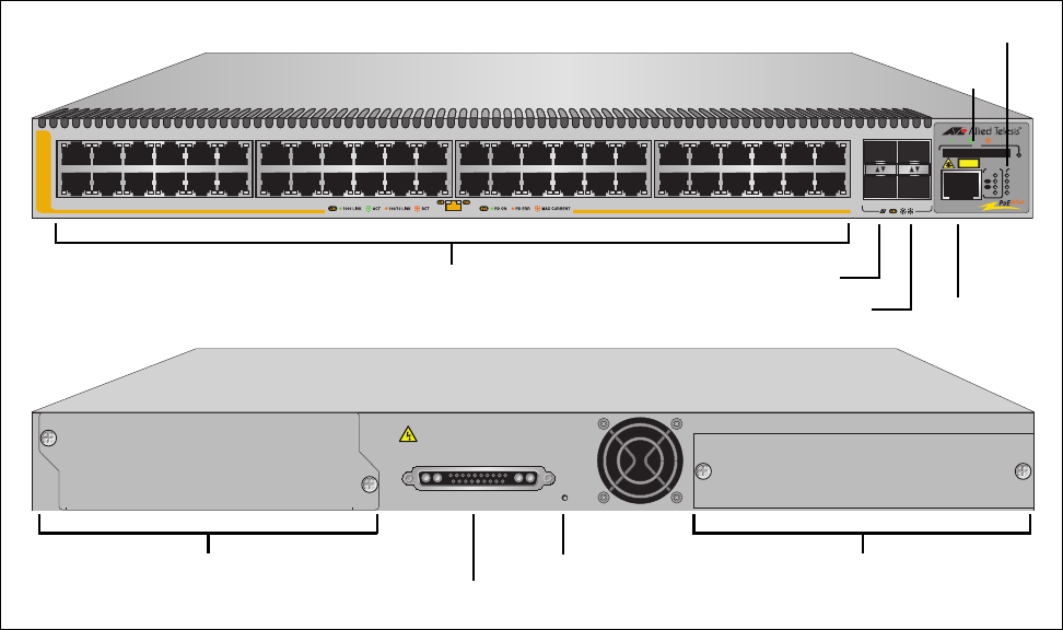
Figure 9 shows the x610-48Ts/X-POE+ switch front and rear panel.
48R38 40 42 44 462 4 6 8 10 12
34
36
32
26 28 30
16
14 22 24
18
20
SFP
49
SFP+
47
47R37 39 41 43 451357911 1513 17 19 21 23 3331 3525 27 29
x610-48Ts/X-POE+
10G
48 50
1000 / 100
SD
STAT US
FAULT
MASTER
RPS
PWR
PRES
MSTR
L/A
L/A
CLASS 1
LASER PRODUCT
1
2
STACK
BUSY
READY
FAULT
CONSOLE
1
0/100/1000Base-T Ports
SFP Slots
System and Stack LEDs
SD Slot
RPS LED
RJ-45
SFP+ Slots
Console Port
POWER SUPPLY
RPS
READY
RPS INPUT
56V/18A MAX 12V/21A MAX
STACKING
WARNING
This unit may have more than one power input. To reduce the risk of
electric shock, disconnect both A/C and RPS inputs before servicing
unit.
AT-L BM
RPS Connector
Power Supply Slot with Blank Panel
Expansion Slot with AT-LBM Module
Figure 9. x610-48Ts/X-POE+ Switch