


2260
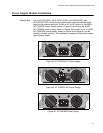
POWER SUPPLY
RPS I
56V/18A MAX
WARNING
This unit may have mor
e
electric shock, disconn
e
unit.
100-240VAC~ 5A MAX
DC PWR
FAULT
AT-PWR250
x610 Series Layer 3 Gigabit Ethernet Switches Installation Guide
83
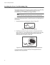
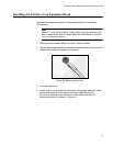
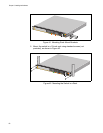
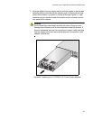
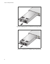
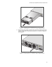
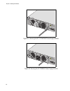
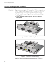
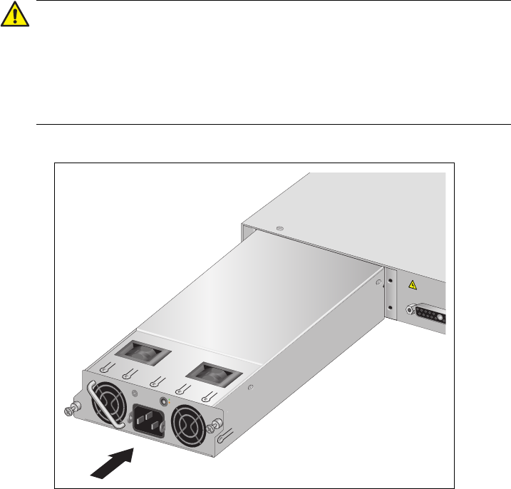
3. Align the edges of power supply module with the guides in the slot and
carefully slide the module into the chassis until it is flush with the rear
panel of the chassis, as shown in Figure 48 through Figure 51. Light
pressure may be needed to seat the module on the connector on the
rear panel of the chassis.
Caution
Do not force the power supply module into place. Doing so may
damage the connector pins on the backplane inside the chassis. If
there is resistance, remove the module and reinsert it after verifying
that the edges of the card are properly aligned in the guides in the
chassis’ module slot.
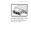
Figure 48. Installing the AT-PWR250 AC Power Supply Module