


2269
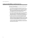
POWER SUPPLY
RPS I
56V/18A MAX
WARNING
This unit may have mor
e
electric shock, disconn
e
unit.
FOR CENTRALIZED DC POWER
CONNECTION, INSTALL ONLY IN A
RESTRICTED AREA.
40-60VDC
6A
OUTPUT POWER
FAULT
AT-PWR250
x610 Series Layer 3 Gigabit Ethernet Switches Installation Guide
105
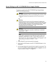
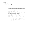
Warning
When installing this equipment, always ensure that the power supply
ground connection is installed first and disconnected last. E11
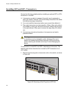
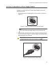
Figure 73. Inserting Wires into a DC Terminal Block
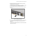
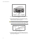
6. Connect the +48 VDC (RTN) feed wire to the terminal block marked
+ (plus).
7. Connect the -48 VDC feed wire to the terminal block marked - (minus).
Warning
Check to see if there are any exposed copper strands coming from
the installed wires. When this installation is done correctly there
should be no exposed copper wire strands extending from the
terminal block. Any exposed wiring can conduct harmful levels of
electricity to persons touching the wires. E12
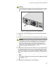
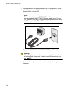
8. Secure the tray cable near the rack framework using multiple cable ties
to minimize the chance of the connections being disturbed by casual
contact with the wiring. Use at least four cable ties, separated 100mm
(4 in.) apart. Locate the first one within 150mm (6 in.) of the terminal
block.
Note
This system will work with a positive grounded or negative grounded
DC system. E13
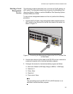
9. Verify that the circuit breaker is in the Off position.