AMD Confidential
User Manual September 12
h
, 2008
226 Appendix A
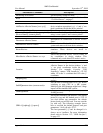
Instruction
Supported
Mnemonic
Opcode
Description
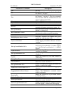
ADDSUBPD xmm1,xmm2/m128
66 0F D0 /r
Add/Subtract packed double-precision
floating-point number from XMM2/Mem
to XMM1.
ADDSUBPS xmm1,xmm2/m128
F2 0F D0 /r
Add/Subtract packed single-precision
floating-point number from XMM2/Mem
to XMM1.
FISTTP m16int
DF /1
Store ST as a signed integer
(truncate) in m16int and pop ST.
FISTTP m32int
DB /1
Store ST as a signed integer
(truncate) in m32int and pop ST.
FISTTP m64int
DD /1
Store ST as a signed integer
(truncate) in m16int and pop ST.
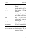
HADDPD xmm1,xmm2/m128
66 0F 7C /r
Add horizontally packed double-
precision floating-point numbers
from XMM2/Mem to XMM1.
HADDPS xmm1,xmm2/m128
F2 0F 7C /r
Add horizontally packed single-
precision floating-point numbers
from XMM2/Mem to XMM1.
HSUBPD xmm1,xmm2/m128
66 0F 7D /r
Subtract horizontally packed double-
precision floating-point numbers
from XMM2/Mem to XMM1.
HSUBPS xmm1,xmm2/m128
F2 0F 7D /r
Subtract horizontally packed single-
precision floating-point numbers
from XMM2/Mem to XMM1.
LDDQU xmm,m128
F2 0F F0 /r
Load 128 bits from Memory to XMM
register.
MONITOR EAX,ECX,EDX
0F 01 C8
Sets up a linear address range to be
monitored by hardware and activates
the monitor. The address range
should be of a write-back memory
caching type.
1
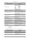
MOVDDUP xmm1,xmm2/m64
F2 0F 12 /r
Move 64 bits representing the lower
double-precision data element from
XMM2/Mem to XMM1 register and
duplicate.
MOVSHDUP xmm1,xmm2/m128
F3 0F 16 /r
Move 128 bits representing packed
single-precision data elements from
XMM2/Mem to XMM1 register and
duplicate high.
MOVSLDUP xmm1,xmm2/m128
F3 0F 12 /r
Move 128 bits representing packed
single-precision data elements from
XMM2/Mem to XMM1 register and
duplicate low.
MWAIT EAX,ECX
0F 01 C9
A hint that allows the processor to
stop instruction execution and enter
an implementation–dependent
optimized state until occurrence of
a class events.
2
Table 15-12: Prescott New Instruction Reference
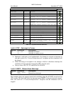
A.6.8.1 MONITOR – Setup Monitor Address
Opcode
Instruction
Description
0F 01 C8
MONITOR
Setup Monitor Address.
The simulator does not recognize this instruction. Therefore the simulator generates an
invalid-opcode exception.
1
See Section A.6.8.1, “MONITOR – Setup Monitor Address”, on page 206.
2
See Section A.6.8.2, “MWAIT – Monitor Wait”, on page 207.


