


Introduction
3
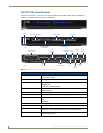
NI-3101-SIG Signature Series NetLinx Integrated Controller
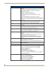
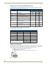
NI-3101-SIG Specifications (Cont.)
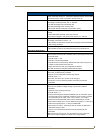
Input/Output LEDs White Output LED blinks when the Controller transmits data, sets channels
On/Off, sends data strings, etc. White Input LED blinks when it receives data
from button pushes, strings, commands, channel levels, etc.
RS-232/422/485 LEDs Six sets of blue and white LEDs light to indicate the rear serial Ports 1 - 6 are
transmitting or receiving RS-232, 422, or 485 data:
• TX LEDs (blue) light when transmitting data
• RX LEDs (white) light when receiving data
• LED activity reflects transmission and reception activity
Relay LEDs Eight blue LEDs light to indicate the rear relay channels 1 - 8 are active
(closed).
• These LEDs reflect the state of the relay on Port 8
• If the relay is engaged = LED On and if the relay is Off = LED Off
IR/Serial LEDs Eight blue LEDs light to indicate the rear IR/Serial channels 1 - 8 are
transmitting control data on Ports 9 - 16.
• LED indicator for each IR port remains lit for the length of time that IR/Serial
data is being generated.
I/O LEDs Eight white LEDs light when the rear I/O channels 1-8 are active
• LED indicator for each I/O port reflects the state of that particular port.
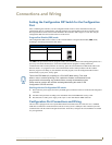
Rear Panel Connectors:
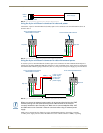
RS-232/422/485 (Ports 1 - 6) Six RS-232/422/485 control ports using DB9 (male) connectors with XON/
XOFF (transmit on/transmit off), CTS/RTS (clear to send/ready to send), and
300-115,200 baud.
• Channel range = 1-255
• Channels 1-254 provide feedback
• Channel 255 (CTS Push channel): Reflects the state of the CTS Input if a
'CTSPSH' command was sent to the port
• Output data format for each port is selected via software
• Six DB9 connectors provide RS-232/422/485 termination
Relay (Port 8) Eight-channel single-pole single-throw relay ports.
• Each relay is independently controlled.
• Supports up to 8 independent external relay devices
• Channel range = 1-8
• Each relay can switch up to 24 VDC or 28 VAC @ 1 A
• Two 8-pin 3.5 mm mini-Phoenix (female) connectors provide relay
termination
Digital I/O (Port 17) Eight-channel binary I/O port for contact closure.
• Each input is capable of voltage sensing. Input format is software
selectable.
• Interactive power sensing for IR ports
• Channel range = 1-8
• All inputs are assigned to respective IR/Serial ports for "automatic" power
control through the use of software commands. Power control is provided
via commands such as: ’PON’, ’POF’, ’POD’, ’DELAY’, I/O Link etc.).
• Contact closure between GND and an I/O port is detected as a PUSH
• When used as voltage input - I/O port detects a low signal (0- 1.5 VDC) as a
PUSH and a high signal (3.5 - 5 VDC) as a RELEASE
• When used as an output - each I/O port acts as a switch to GND and is
rated at 200 mA @ 12 VDC
• 10-pin 3.5 mm mini-Phoenix (female) connector provides I/O port
termination
Note: This IO port uses 5V logic, but can handle up to 12V on the input
without harm. Higher voltages run a higher risk of surge damage.