


Connections and Wiring
8
NI-3101-SIG Signature Series NetLinx Integrated Controller
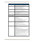
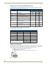
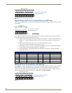
Modes and Front Panel LED Blink Patterns
The following table lists the modes and blink patterns for the front panel LEDs associated with each mode.
These patterns are not evident until after the unit is powered.
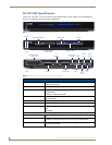
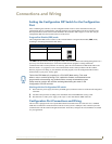
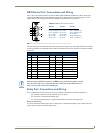
Port Assignments and Functionality
The rear Port Assignments are as follows:
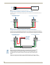
AXlink Port and LED
All NI units have an AXlink port and adjacent status LED (FIG. 3). This port allows the NI to support AMX
legacy AXlink devices such as G3 touch panels (ex: CP4/A) and PosiTrack Pilot devices. A green LED shows
AXlink data activity. When the AXlink port is operating normally, blink patterns include:
Off - No power, or the controller is not functioning properly.
1 blink per second - Normal operation.
3 blinks per second - AXlink bus error. Check all AXlink bus connections.
Modes and LED Blink Patterns
LEDs and Blink Patterns
Mode Description
STATUS
(blue)
OUTPUT
(white)
INPUT
(white)
OS Start Starting the operating system (OS). On On On
Boot On-board Master is booting. On Off On
Contacting DHCP
server
On-board Master is contacting a DHCP
server for IP configuration information.
On Off Fast Blink
Unknown DHCP
server
On-board Master could not find the DHCP
server.
Fast Blink Off Off
Downloading Boot
firmware
Downloading Boot firmware to the Master’s
on-board flash memory.
Do not cycle power during this process!
Fast Blink Fast Blink Fast Blink
No program running Either no program is loaded, or the
program is disabled.
On Normal Normal
Normal On-board Master is functioning normally. 1 blink per
second
Indicates
activity
Indicates
activity
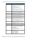
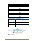
NI-3101 Port Assignments
Port ICSP Port # Port ICSP Port #
Serial Port #1 1 IR Serial Port #1 9
Serial Port #2 2 IR Serial Port #2 10
Serial Port #3 3 IR Serial Port #3 11
Serial Port #4 4 IR Serial Port #4 12
Serial Port #5 5 IR Serial Port #5 13
Serial Port #6 6 IR Serial Port #6 14
Relays Ports (1-8) 8 IR Serial Port #7 15
IR Serial Port #8 16
I/O Port 17
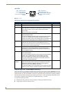
FIG. 3
AXlink connector and LED
GND
AXM
AXP
PWR
AXLink