


Connections and Wiring
11
NI-3101-SIG Signature Series NetLinx Integrated Controller
DB9 Device Port: Connections and Wiring
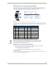
FIG. 7 shows the connector pinouts for the rear RS-232/RS-422/RS-485 (DB9) Device Ports. These ports
support most standard RS-232 communication protocols for data transmission. This figure gives a visual
representation of the wiring specifications for the RS-232/422/485 Device connectors.
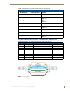
The table below provides information about the connector pins, signal types, and signal functions. This table’s
wiring specifications are applicable to the rear RS-232/422/485 Device Port connectors on the NI-3101-SIG
(Ports 1-6).
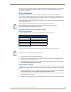
Relay Port: Connections and Wiring
Up to 8 independent external relay devices may be connected to the Relay connectors on the device.
Connectors labeled A are for common; B are for output.
Each relay is isolated and normally open.
A metal commoning strip is supplied with each device to connect multiple relays.
Relay connections
Use A for common and B for output (FIG. 8). Each relay is isolated and normally open. A metal connector
strip is also provided to common multiple relays.
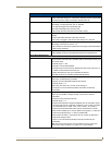
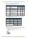
FIG. 7 RS-232/422/485 DB9 (male) connector pinouts for the rear Device Ports
RS-232/422/485 Device Port Wiring Specifications
Pin Signal Function RS-232 RS-422 RS-485
1 RX- Receive data X X (strap to pin 9)
2 RXD Receive data X
3 TXD Transmit data X
4 TX+ Transmit data X X (strap to pin 6)
5 GND Signal ground X X
6 RX+ Receive data X X (strap to pin 4)
7 RTS Request to send X
8 CTS Clear to send X
9 TX- Transmit data X X (strap to pin 1)
5
4
3
2
1
9
8
7
6
Male
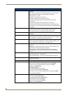
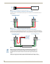
DB9 Serial Port pinouts (male connector)
Pin 2: RX signal
Pin 3: TX signal
Pin 5: GND
Pin 7: RTS
Pin 8: CTS
RS-232
Pin 1: RX -
Pin 4: TX +
Pin 5: GND
Pin 6: RX +
Pin 9: TX -
RS-422
Pin 1: A (strap to 9)
Pin 4: B (strap to 6)
Pin 5: GND
Pin 6: B (strap to 4)
Pin 9: A (strap to 1)
RS-485
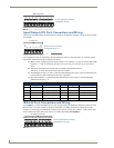
When wiring the 422/485 connections, do NOT use pre-made 9-wire cable or connect
the wire in the cable to any connection that will not be used by the DB9 serial port.
Only use wiring that connects the needed pins.