


Connections and Wiring
13
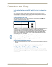
NI-3101-SIG Signature Series NetLinx Integrated Controller
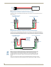
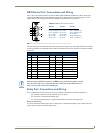
The IR/Serial connector wiring specifications are listed in the following table:
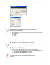
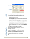
LAN (Ethernet/RJ-45 Port): Connections and Wiring
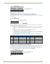
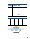
The following table lists the pinouts, signals, and pairing for the LAN connector.
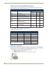
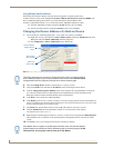
FIG. 11 diagrams the RJ-45 pinouts and signals for the LAN RJ-45 connector and cable.
IR/Serial Connector Wiring Specifications (per Port)
Number of
IR connections NI-3101-SIG Port # Function
1 9 GND (-)
Signal 1 (+)
2 10 GND (-)
Signal 2 (+)
3 11 GND (-)
Signal 3 (+)
4 12 GND (-)
Signal 4 (+)
5 13 GND (-)
Signal 5 (+)
6 14 GND (-)
Signal 6 (+)
7 15 GND (-)
Signal 7 (+)
8 16 GND (-)
Signal 8 (+)
LAN RJ-45 Pinouts and Signals
Pin Signals Connections Pairing Color
1 TX + 1 --------- 1 1 --------- 2 Orange-White
2 TX - 2 --------- 2 Orange
3 RX + 3 --------- 3 3 --------- 6 Green-White
4 no connection 4 --------- 4 Blue
5 no connection 5 --------- 5 Blue-White
6 RX - 6 --------- 6 Green
7 no connection 7 --------- 7 Brown-White
8 no connection 8 --------- 8 Brown
FIG. 11
RJ-45 wiring diagram