


Table of Contents
i
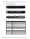
NI-3101-SIG Signature Series NetLinx Integrated Controller
Table of Contents
Introduction ........................................................................................................1
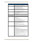
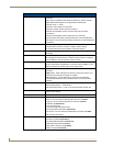
NI-3101-SIG Specifications........................................................................................ 2
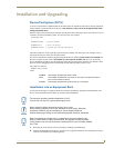
Installation and Upgrading .................................................................................5
Device:Port:System (D:P:S) ....................................................................................... 5
Installation into an Equipment Rack.......................................................................... 5
Connections and Wiring .....................................................................................7
Setting the Configuration DIP Switch for the Configuration Port............................. 7
Program Run Disable (PRD) mode................................................................................... 7
Working with the Configuration DIP switch .................................................................... 7
Configuration Port Connections and Wiring ............................................................. 7
Modes and Front Panel LED Blink Patterns .............................................................. 8
Port Assignments and Functionality.......................................................................... 8
AXlink Port and LED ................................................................................................. 8
Wiring Guidelines ..................................................................................................... 9
Wiring length guidelines ................................................................................................. 9
Preparing captive wires................................................................................................... 9
Wiring a power connection ............................................................................................. 9
Using the 4-pin mini-Phoenix connector for data and power ........................................ 10
Using the 4-pin mini-Phoenix connector for data with external power ......................... 10
DB9 Device Port: Connections and Wiring ............................................................. 11
Relay Port: Connections and Wiring ....................................................................... 11
Relay connections.......................................................................................................... 11
Input/Output (I/O) Port: Connections and Wiring................................................... 12
IR/Serial Port: Connections and Wiring................................................................... 12
LAN (Ethernet/RJ-45 Port): Connections and Wiring .............................................. 13
LAN LEDs ..................................................................................................................... 14
LAN ports used by the Integrated Controllers.............................................................. 14
Replacing the Timekeeper Battery ......................................................................... 14
Configuration and Firmware Update ................................................................17
Overview ................................................................................................................ 17
Communicating with the Master via the Program Port........................................... 17
Setting the System Value........................................................................................ 18
Using Multiple NetLinx Masters .................................................................................... 20
Changing the Device Address of a NetLinx Device ................................................ 20
Recommended NetLinx Device Numbers...................................................................... 21
Using the ID Button to Change the Controller’s Device Value ............................... 21