


NXA-AVB/ETHERNET Breakout Box
9
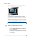
7" Modero Widescreen Touch Panels
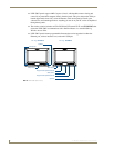
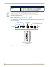
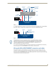
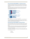
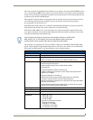
A 12 VDC-compliant power supply can also directly provide power through the unit to a target Modero
panel. FIG. 6 shows a sample wiring configuration for a non-video capable Modero panel.
Use a standard CAT5 Ethernet cable to provide both communication and 10/100 network connectivity
between the panel, NXA-AVB/ETHERNET, NetLinx Master, and the network.
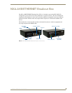
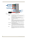
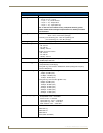
Wiring the NXA-AVB/ETHERNET connectors and cables
The inputs and outputs on the breakout box are separated into front and rear connectors. The rear
connectors are used to input external signals. The front connectors are used to communicate signals
between the NXA-AVB/ETHERNET and a target Modero panel. FIG. 7 provides a layout of the wiring
connection both into and from the breakout box.
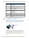
FIG. 5 Sample wiring configuration on video-capable panels using this breakout box
FIG. 6 Sample wiring configuration using non-video capable Modero panels
NXD/T Video-capable
Ethernet In
12 VDC power
(RJ-45)
Video In
(BNC)
Mic Out
(4-pin captive-wire)
Audio In
(6-pin captive-wire)
NXA-AVB/ETHERNET
Power
supplied via
NXA-AVB box
Audio/Video
(CAT5)
Line Level out
(to amplifier
or VOL card)
Touch Panels
or
Direct
Connect
Breakout Box
Ethernet
(rear)
(front)
(CAT5)
supply
Indirect
Connect
12 VDC power
supply
Direct
connect
NXD/T Non-video capable
Ethernet
(CAT5)
Touch Panels
12 VDC power
Audio (CAT5)
between the
NXA-AVB/ETHERNET
Breakout Box
supply
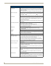
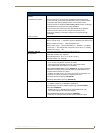
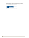
The breakout box unit can be mounted on either a horizontal flat surface or into an
equipment rack (by removing the front screws and attaching it to an optional AC-RK).
The power supply being used on the NXA-AVB/ETHERNET is dependant on the
power requirements of the target touch panel.