


Introduction
ARM DUI 0163B Copyright © 2001-2003. All rights reserved. 1-5
1.2.2 Architecture
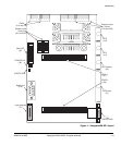
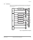
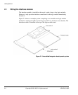
Figure 1-2 shows the architecture of the interface module. For more detail on signal
routing between the expansion connectors and the interface circuits, see Chapter 3
Hardware Reference.
Figure 1-2 Integrator/IM-AD1 block diagram
J3A
J3B
J19
J23
Stepper motor
interfaces
D to A converter
A to D converter
J2
J1
UART interface
CAN interfaces
J14
J18
EXPA
socket
EXPIM
socket
J10
PWMs
J17
J16
SERIAL
GPIOA
GPIOB
DC/
PWM1
DC/
PWM2
A/D
IN
D/A OUT
CAN2
CAN1
STEP2
STEP1
EXPB
socket
J11
J13
SPI1
SPI2
J21
J22
STEP3
STEP4