


Hardware Reference
3-6 Copyright © 2001-2003. All rights reserved. ARM DUI 0163B
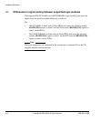
3.4 PWM interface
The interface module is fitted with a dual MOSFET switch. This provides two outputs
that can be configured as Pulse Width Modulated (PWM) outputs or used as DC
switches to switch external loads.
The MOSFET can switch loads at up to 30V. Although the MOSFET is rated for 3A,
because of the power dissipation of the package the maximum load current is 2.5A if
only one PWM output is used or 1.75A if both outputs are used.
Warning
The device U21, fitted to the underside of the PCB, and the surrounding area of the
board becomes very hot when high load currents are used.
As a PWM output, the interfaces can be driven by the DC-DC PrimeCell (PL160). The
DC-DC PrimeCell has feedback inputs that negate the drive outputs when LOW. These
inputs can be used to implement a current limit with external circuitry.
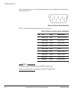
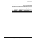
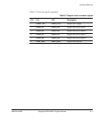
Table 3-4 shows the assignment of the PWM interface signals to the logic module
signals on the EXPIM connector.
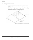
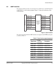
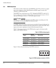
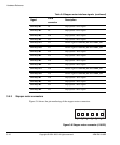
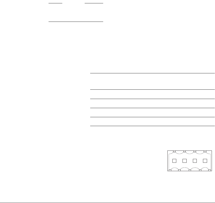
Figure 3-4 shows the pin numbering of the PWM connectors.
Figure 3-4 PWM interface connector (J10/J14)
Table 3-4 PWM interface signals
Signal
EXPIM
connector
Description
PWM1_DRIVE IM_BBANK37 PWM1 switch control signal
PWM2_DRIVE IM_BBANK38 PWM2 switch control signal
PWM1_FB IM_BBANK39 PWM1 feedback
PWM2_FB IM_BBANK40 PWM2 feedback
1234