


Reference Design Example
4-6 Copyright © 2001-2003. All rights reserved. ARM DUI 0163B
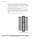
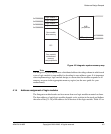
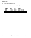
page 4-6 shows the values of address bits [31:28] on logic modules fitted to an
Integrator/AP in the EXPA/EXPB connector position (see the Integrator/AP User
Guide for more information).
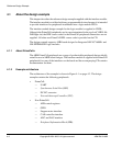
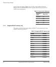
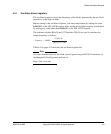
4.1.5 Integrator/IM-AD1 memory map
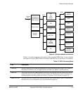
The memory model for the design is shown in Table 4-2 and assumes that the logic
module is mounted in position 0.
Table 4-2 Logic module addresses
Position in
stack
Bits 31:28
0 (bottom)
0xC
1
0xD
2
0xE
3 (top)
0xF
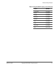
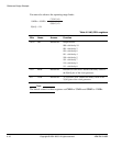
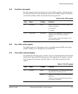
Table 4-3 Integrator/IM-AD1 memory map
Device Address
logic module APB registers
0xC0000000
UART0
0xC0100000
SPICS
0xC0200000
SSP
0xC0300000
Reserved
0xC0400000
Reserved
0xC0500000
Reserved
0xC0600000
Reserved
0xC0700000
Reserved
0xC0800000
Reserved
0xC0900000
DCDC
0xC0A00000
STEPPERA
0xC0B00000