


Hardware Reference
3-14 Copyright © 2001-2003. All rights reserved. ARM DUI 0163B
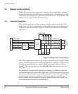
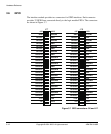
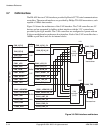
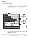
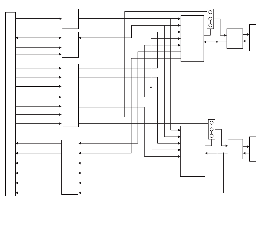
3.7 CAN interface
The IM-AD1 has two CAN interfaces provided by Bosch CC770 serial communications
controllers. The network interfaces are provided by Philips TJA1050 transceivers, each
capable of 1Mb/s data transfer.
Figure 3-8 shows the architecture of the CAN interface. The CAN controllers are 5V
devices and are supported by buffers at their interface with the 3.3V system buses
provided by the logic module. The CAN controllers are configured to operate with an
8-bit non-multiplexed asynchronous host interface. Each of the CAN controllers has a
16MHz crystal that it uses for its internal clocks.
Figure 3-8 CAN interface architecture
EXPIM Socket
CAN
controller
(U14)
CAN
controller
(U18)
CAN_R/nW_5V
U17
U20
U13
U16
CAN2_nCS_5V
CAN1_nCS_5V
CAN1_RESET_5V
CAN2_RESET_5V
CAN1_nDSACK0_5V
CAN2_nDSACK0_5V
CAN1_nINT_5V
CAN2_nINT_5V
CAN_A[7:0]_5V
CAN_D[7:0]_5V
CAN2_nCS
CAN1_nCS
CAN1_RESET
CAN2_RESET
CAN1_nDSACK0
CAN2_nDSACK0
CAN1_nINT
CAN2_nINT
CAN_A[7:0]
CAN_D[7:0]
CAN_T/R
CAN_nOE
J3A
J3B
U13
U15
U19
CAN_R/nW
CAN1_TXD
CAN2_TXD
CAN1_TXD_5V
CAN2_TXD_5V
CAN1_RXD
CAN2_RXD
CAN1_RXD_5V
CAN2_RXD_5V
LK1
LK2
CAN2_TXD
Buffer
Buffer
Buffer
Buffer
CAN
transceiver
CAN
transceiver
CAN1_TXD