


Getting Started
ARM DUI 0163B Copyright © 2001-2003. All rights reserved. 2-3
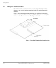
2.2 Setting up the logic module
You must load the required peripheral controllers into the logic module FPGA to drive
the interfaces. The interface module is supplied with example configurations that
provide PrimeCell peripherals for supported logic modules.
The logic module can be programmed using Multi-ICE with or without the IM-AD1
fitted. If the IM-AD1 is fitted however, the manufacturer-specific download connector
on the logic module is inaccessible. See the logic module user guide for detailed
instructions on downloading new FPGA configurations
To download the supplied example logic module FPGA configuration using Multi-ICE:
1. Insert CONFIG link on the logic module (or IM-AD1 if fitted to logic module).
2. Connect Multi-ICE unit to J10 on the logic module (or J9 on the IM-AD1).
3. Power up the Integrator system.
4. Start the Multi-ICE server on your PC and click the
Autoconfigure
button.
5. If you are using an Altera logic module, LM-EP20K1000E, switch 4 of
switchpack S1 must be set to the CLOSED position.
6. Browse to:
Install_directory\IM-AD1\configure
.
7. Double-click the
progcards.exe
program file.
8. The
progcards
program automatically detects whether the logic module is an
Altera or a Xilinx module and uses the appropriate
.brd
file to download the
configuration file.
9. After the programming has completed:
• power down the system
• remove the CONFIG link
• move the Multi-ICE connection to the core module.
10. Set the S1 switches on the logic module as follows:
Switch 1 Open
Switch 2 Closed
Switch 3 Open
Switch 4 Open.
The logic module will now be configured with the example design.
If the IM-AD1 is not already fitted, install it on top of the logic module and the system
is ready to use.