


Hardware Reference
ARM DUI 0163B Copyright © 2001-2003. All rights reserved. 3-9
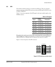
The current limit is set by the reference voltage and sense resistor according to the
equation:
Therefore, with a 0.1Ω sense resistor fitted:
The reference voltage, and therefore the current limit, can be adjusted by altering the
values of the divider resistors. Although the DC current switching limit of L298 is 2A,
due to the power dissipation limit of the device and the heatsink, the maximum load
current for each stepper winding is 1.5A. The L298 can switch drive voltages up to 46V.
Warning
The L298 devices, U24 and U26, and their heatsinks are very hot when high load
currents are used.
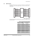
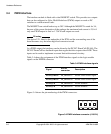
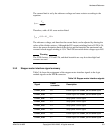
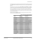
3.5.2 Stepper motor interface signal summary
Table 3-6 shows the assignment of the stepper motor interface signals to the logic
module signals on the EXPB connector.
I
peak
=
V
ref
R
sense
I
peak
=
0.15 x 10
=
1.5A
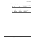
Table 3-6 Stepper motor interface signals
Signal
EXPB
connector
Description
STEP1_ENA F0 Enable signal for STEP1_O1 and STEP1_O2
STEP1_ENB F1 Enable signal for STEP1_O3 and STEP1_O4
STEP1_PH1 F2 Step1 phase 1 drive signal
STEP1_PH2 F3 Step1 phase 2 drive signal
STEP1_PH3 F4 Step1 phase 3 drive signal
STEP1_PH4 F5 Step1 phase 4 drive signal
STEP2_ENA F6 Enable signal for STEP2_O1 and STEP2_O2
STEP2_ENB F7 Enable signal for STEP2_O3 and STEP2_O4