


Hardware Reference
3-4 Copyright © 2001-2003. All rights reserved. ARM DUI 0163B
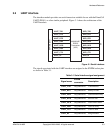
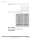
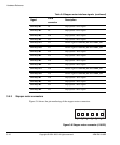
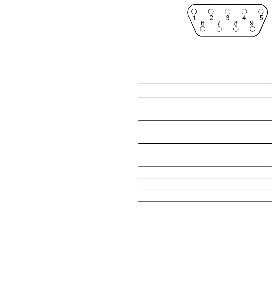
The serial interface uses a 9-pin D-type male connector for which the pin numbering is
shown in Figure 3-2.
Figure 3-2 Serial connector pinout
Table 3-2 shows the signal assignment for the connector.
Note
The serial interfaces signals operate at RS232 signal levels.
Serial port functionality corresponds to the DTE configuration.
Table 3-2 Serial connector signal assignment
Pin J18 Type Description
1 SER_DCD Input Data carrier detect
2 SER_RXD Input Receive data
3 SER_TXD Output Transmit data
4 SER_DTR Output Data terminal ready
5 SER_GND Input ground
6 SER_DSR Input Data set ready
7 SER_RTS Output Ready to send
8 SER_CTS Input Clear to send
9 SER_RI Input Ring indicator