


ASUS TW510-E2ASUS TW510-E2
ASUS TW510-E2ASUS TW510-E2
ASUS TW510-E2
5-235-23
5-235-23
5-23
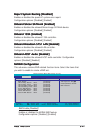
Min RAS# Active Time (Tras) [ 8T]Min RAS# Active Time (Tras) [ 8T]
Min RAS# Active Time (Tras) [ 8T]Min RAS# Active Time (Tras) [ 8T]
Min RAS# Active Time (Tras) [ 8T]
Controls the number of DRAM clocks used for DRAM parameters.
Configuration options: [5T] [6T] [7T] [8T] [9T] [10T] [11T] [12T] [13T]
[14T] [15T]
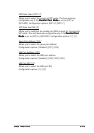
RAS# to CAS# Delay (Trcd) [ 4T]RAS# to CAS# Delay (Trcd) [ 4T]
RAS# to CAS# Delay (Trcd) [ 4T]RAS# to CAS# Delay (Trcd) [ 4T]
RAS# to CAS# Delay (Trcd) [ 4T]
Controls the latency between the DRAM active command and the read/
write command. Configuration options: [2T] [3T] [4T] [5T] [6T] [7T]
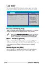
Row Precharge Time (Trp) [ 2T]Row Precharge Time (Trp) [ 2T]
Row Precharge Time (Trp) [ 2T]Row Precharge Time (Trp) [ 2T]
Row Precharge Time (Trp) [ 2T]
Controls the idle clocks after issuing a precharge command to the DRAM.
Configuration options: [2T] [3T] [4T] [5T] [6T] [7T]
Node Memory Interleaving [Disabled]Node Memory Interleaving [Disabled]
Node Memory Interleaving [Disabled]Node Memory Interleaving [Disabled]
Node Memory Interleaving [Disabled]
Enables or disables memory interleaving. Configuration options: [Disabled]
[Enabled]
S/W Memory Hole Remapping [Enabled]S/W Memory Hole Remapping [Enabled]
S/W Memory Hole Remapping [Enabled]S/W Memory Hole Remapping [Enabled]
S/W Memory Hole Remapping [Enabled]
Allows memory hoisting/remapping of the memory-mapped I/O address hole
to above 4GB system memory. Configuration options: [Disabled] [Enabled]
MTRR Mapping Mode [Continuous]MTRR Mapping Mode [Continuous]
MTRR Mapping Mode [Continuous]MTRR Mapping Mode [Continuous]
MTRR Mapping Mode [Continuous]
Allows selection of [Continuous] for standard mode, or [Discreet] for
aggressive mode. Configuration options: [Continuous] [Discreet]
Master ECC Enable [Enabled]Master ECC Enable [Enabled]
Master ECC Enable [Enabled]Master ECC Enable [Enabled]
Master ECC Enable [Enabled]
Enables or disables ECC check/correct mode. Configuration options:
[Disabled] [Enabled]
ECC Memory Interlock [At Least One]ECC Memory Interlock [At Least One]
ECC Memory Interlock [At Least One]ECC Memory Interlock [At Least One]
ECC Memory Interlock [At Least One]
Allows selection for DIMMs that are ECC-compliant. Configuration options:
[At Least One] [All are]
ECC MCE Enable [Disabled]ECC MCE Enable [Disabled]
ECC MCE Enable [Disabled]ECC MCE Enable [Disabled]
ECC MCE Enable [Disabled]
When set to [Enabled], a machine-check exception (#MC) occurs whenever
an machine-check error that may not be corrected is encountered.
Configuration options: [Disabled] [Enabled]
Chip-Kill Mode Enable [Disabled]Chip-Kill Mode Enable [Disabled]
Chip-Kill Mode Enable [Disabled]Chip-Kill Mode Enable [Disabled]
Chip-Kill Mode Enable [Disabled]
When set to [Enabled], allows ECC checking to be based on a 128/16
data/ECC rather than on a 64/8 data/ECC. You may only enable this
feature in 128-bit DRAM data width mode. Configuration options:
[Disabled] [Enabled]