


2-272-27
2-272-27
2-27
ASUS TW510-E2ASUS TW510-E2
ASUS TW510-E2ASUS TW510-E2
ASUS TW510-E2
Back sideBack side
Back sideBack side
Back side
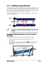
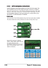
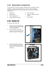
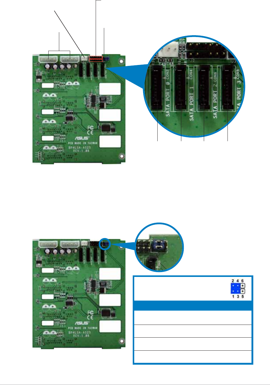
The back side of SATA backplane faces the rear panel when installed. This
side includes the power and HDD fan connectors, jumper, SATA interfaces,
and SMBus connectors.
SMBus connector SMBus connector
SMBus connector SMBus connector
SMBus connector (upper 6-1 pins)
(connects the SMB cable from the motherboard)
Fan connectorFan connector
Fan connectorFan connector
Fan connector
(for HDD fan)
Power connectorsPower connectors
Power connectorsPower connectors
Power connectors
(connect power plugs
from the power supply)
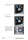
CON2CON2
CON2CON2
CON2
CON4CON4
CON4CON4
CON4
CON6CON6
CON6CON6
CON6
CON8CON8
CON8CON8
CON8
Power SMBus connector Power SMBus connector
Power SMBus connector Power SMBus connector
Power SMBus connector (lower 6-1 pins)
(connects the SMB cable from the power supply, when available)
SATA backplane jumper settings and HDD ID assignmentsSATA backplane jumper settings and HDD ID assignments
SATA backplane jumper settings and HDD ID assignmentsSATA backplane jumper settings and HDD ID assignments
SATA backplane jumper settings and HDD ID assignments
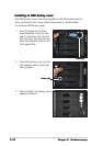
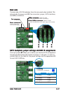
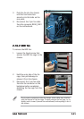
The 6-pin jumper
J1 J1
J1 J1
J 1 allows you to define your desired SATA configuration.
The picture below shows the location of jumper J1 with pins 1-3 and 2-4
shorted. Refer to the table for the jumper settings and the appropriate ID#
for each SATA HDD bay.
J1 settingJ1 setting
J1 settingJ1 setting
J1 setting
(1-3 shorted, 2-4 shorted)
DeviceDevice
DeviceDevice
Device
SATA BP IDSATA BP ID
SATA BP IDSATA BP ID
SATA BP ID
Drive Bay 1 CON2
Drive Bay 2 CON4
Drive Bay 3 CON6
Drive Bay 4 CON8