


7
ATTO Technology Inc. Diamond Storage Array Installation and Operation Manual
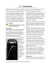
3.1 Components
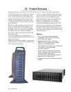
The Diamond Storage Array has been designed to be easy to use, maintain and upgrade. It features a
durable steel outer case and modular components in either a floor or a rack mount model.
Immediately upon receipt, check the shipping
carton for damage from mishandling. Contact us
at once via the means that is easiest for you (refer
to
Warranty
on page xvi) if the carton has been
mishandled or displays any signs of damage.
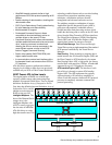
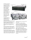
The front of the Diamond Storage Array provides
access to the management card and disk drive
sleds. The rear of the unit holds the host interface
cards, power supplies and blower assemblies.
CAUTIONCAUTION
All modular components must be replaced
by qualified personnel only.
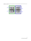
Floor model
The management system card is at the top front of
the case. At its center is a DB-9 serial RS-232
port, a connection for setup, monitoring and
upgrade of the unit from any computer system
with an RS-232 interface. The optional 10/100
BaseT Ethernet management services card
enables Telnet-based monitoring and
management. It
also provides
the ability to
update the
firmware in the
array via FTP.
LEDs to the
port’s right
indicate fault,
unit ready, host
interface cards
A and B
installation
status, and the
power status for
each power
supply.
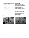
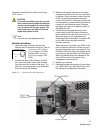
Below the management system card are
individual disk drive sleds which also have LEDs
for each drive’s status. Each sled contains two
hard drives. Up to 24 hard drives may be installed
on the 12 sleds. Empty bays should be covered by
blank faceplates or empty sleds. Access is
provided by loosening two screws and gently
pulling on the sled handle.
On the rear of the unit are blowers which support
hard drive, cabinet and power supply cooling. The
blowers are held in by removable screws. Correct
operation is displayed by a LED at the top of each
panel.
The power supplies for the array, also in the rear
of the unit, are accessible by loosening two screws
and pulling on the power supply module handle.
The power standby on/off switch is at the top of
each module. A yellow LED indicates
caution
and a green LED indicates
on
. The power cord
socket is at the bottom of each power supply.
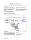
Between the power supplies and blower
assemblies are two slots that hold the Host
Interface cards. The HIC is the connection point
into the array and is available in three options: 1-
Gigabit Fibre Channel, 2-Gigabit Fibre Channel,
or Ultra 160 SCSI. Host Interface cards have
fault
and
on-line
or
fault
and
activity
LED indicators,
depending on the model.
SCSI
The SCSI card faceplate has a rotary
binary-coded hex switch to set the SCSI ID of the
array. The SCSI card also has an in channel, to
connect via cable to the unit’s communication
source, and an out channel, available for daisy-
chaining arrays together or to complete
termination using an external LVD terminator.
Rack mount
The system management card is at the left front of
the case. At its center is a DB-9 serial RS-232 port