


85
ATTO Technology Inc. Diamond Storage Array Installation and Operation Manual
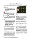
9.0 Hardware Maintenance
The disk drive sleds, blower assemblies, power supplies, host interface cards, and system management
card may be replaced with identical or upgraded parts.
CAUTIONCAUTION
Do not leave empty openings on the front
or rear of the Diamond Storage Array under
any circumstances. Empty openings affect
airflow and may cause the unit to overheat
and shut down.
WARNING
The only way to completely de-energize the unit is
to turn off both power
supplies and unplug both
power cords from the
back of the unit. Turning
the power switch to the
Stand-by position on one
power supply does not
completely turn off power
to the array; it is not an AC on-off switch. Power
may still be in the unit through the other power
supply.
All modular components must be replaced
by qualified personnel only. Use a static
wriststrap when handling any of the cards
inside the Diamond Storage Array.
Components are electrostatic sensitive.
Use proper grounding methods when
working with or around the Diamond
Storage Array. Always store spare
components in proper ESD containers
when not in use.
• The power supply and blower assembly may be
replaced while the unit is running. (refer to
Hot
Swap Operating Instructions on page 87
)
• Host interface cards and management cards
may only be replaced when the array is
off.
Backup the unit fully before replacing these
components.
• You may remove a disk drive sled while the array
is powered on.Refer to the instructions in
Hot
Swap Operating Instructions on page 87
for details.
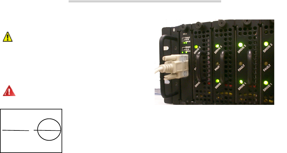
Management card:
To remove a management
card, power down both power supplies, loosen the
screws holding the card in place, pull out the
assembly and replace it with another. Securely
tighten all screws after replacing the component.
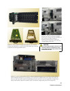
Disk drive sled:
To remove a disk drive sled
(Exhibit 9-2), loosen the screws on either side of
the assembly, then pull on the assembly’s handle
and carefully slide it out of its bay.
FC or SCSI Host Interface Card
To remove a
Fibre Channel or SCSI Host Interface Card from
the back of the array (Exhibit 9-3), power down
both power supplies and remove any cable
attached to the port. Loosen the retaining screws
and pull the Host Interface Card out of the unit. To
replace the card, push it back into the unit and
tighten the retaining screws.
Power supply:
To remove the power supply
(Exhibit 9-4), press the Stand-by power switch to
the off position, remove the power cord, and,
using a No. 1 Phillips screwdriver, loosen the
screws holding the assembly in place. Pull out the
assembly and replace it with another. Securely
tighten all screws after replacing the component.
Blower assembly:
To remove a blower assembly
(Exhibit 9-4), using a No. 1 Phillips screwdriver,
loosen the screws holding the assembly in place.
Pull out the assembly and replace it with another.
Securely tighten all screws after replacing the
component.
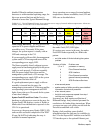
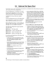
Power Switch Positions
On Stand-by
E
xhibit 9-1: The management card may be accessed via a
s
erial port DB-9 connector or an optional Ethernet
connection.