


10
Physical setup
centermost mounting holes and secured using
10/32 screws.
CAUTIONCAUTION
Do not mount multiple arrays on a two-rail
rack or mount the array above the midpoint
of a two-rail rack system. Do not mount the
array on any kind of rail-type system. The
array is too heavy and does not have the
proper hole pattern for rails.
Note
Insure the array has adequate air flow.
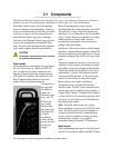
General Instructions
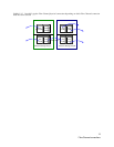
1 Insert the proper connector into the Host
Interface Card in the back of the array. (refer to
Connecting a Fibre Channel
Array
on page 11 for Fibre
Channel and
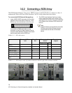
Connecting a
SCSI Array
on page 13 for
SCSI).
2 Connect the cable (Fibre Channel or SCSI)
from your host system to the Host Interface
Card connector on the back of the array. The
cable you use depends upon your application,
the environment and distance.
3 Make sure the power switches on the power
supplies on the rear of the unit are in the stand-
by position. Plug in the power cords to the back
of the unit, then into an appropriate power
source (100-240 VAC). The power source must
be connected to a protective earth ground and
comply with local electrical codes. Improper
grounding may result in an electrical shock or
damage to the unit.
4 Press the stand-by power switch for each
power supply to the ON position. When the
green power LED on the back of the unit is lit,
the power supply is fully operational and
delivering power to the system. The power LED
on the front of the array lights while the
firmware executes.
When the power is turned on, the LEDs on the
front of the array flash twice. Drives spin up in
groups of three every one to two seconds. The
individual LEDs blink. After all available drives
have spun up, the individual drive LEDs stay lit.
When all available drives are operational, the
ready LED on the top front panel of the
management card remains lit.
5 Reboot your computer
6 Determine the best configuration for your needs
(i.e. JBOD, RAID, etc.) and refer to the rest of
this manual for configuration information.
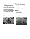
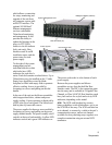
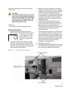
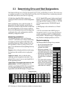
Exhibit 3.2-1 Back side of a rack mount array.
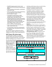
Power Switch Positions
On Stand-by