


88
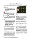
Hot swap hardware
12 If you do not have
AutoRebuild enabled
, using
the disk drive sled number identified in step 2,
on the control computer
Ready prompt type:
ClearDiskReservedArea (SledNum, 1)
ClearDiskReservedArea (SledNum, 2)
Set AtaDiskState (SledNum, 1, ONLINE)
Set AtaDiskState (SledNum, 2, ONLINE)
ResolveLUNConflicts
13 The new disk drive sled is available for system
use 10 to 15 seconds after the disk drives spin
up and communication is reestablished.
Power Supplies
CAUTIONCAUTION
Do not leave empty openings on the front or rear
of the array under any circumstances. Empty
openings may cause the unit to overheat.
WARNING
Hazardous voltage and stored energy hazard
when removing power supplies.
In a system with at least one operational power supply,
the other power supply can be successfully removed
and replaced without powering the system down and
with no loss of array functionality. The green activity
LED on the front of the system management card
identifies the operational status of each power supply
(Green means the power supply is operating
correctly).
Note
System command overlap is discontinued
across some drives when only one power
supply is operational.
Labels on the rear of the array point to the A
and B power supplies.
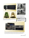
1 Identify the power supply to be swapped.
2 Turn off the power supply on/off switch.
3 Disconnect AC line cord.
4 Unscrew the two screws on the power supply
with the appropriate tool.
5 Pull the power supply out of the chassis using
the power supply module handle.
6 Install a new power supply in the chassis. The
power supply is keyed and can only be inserted
one way.
7 Tighten the two screws on the power supply
with the appropriate tool.
8 Connect AC line cord
9 Turn on the power supply switch.
10 Verify correct operation by observing that the
green light on the rear of the power supply is lit
and the appropriate power supply light on the
system management card on the front of the
unit is lit.
Note
It takes up to 30 seconds for the system to
recognize the insertion or removal of a power
supply and change the LED on the system
management board. The CLI issues
messages about the change (refer to
System
Monitoring and Reporting
on page 77).
Blower Assemblies
CAUTIONCAUTION
Do not leave empty openings on the front or rear
of the array under any circumstances. Empty
openings affect airflow and may cause the unit to
overheat and shut down.
The array contains two blower assemblies. The
blowers are critical to proper array cooling operation.
However, the array can operate with only one
functional blower within certain ambient
temperatures. The blowers are electronically
connected to the power supplies and a power supply
will not run without its corresponding blower: if the
blower adjacent to power supply A is removed, the ‘A’
power supply shuts down, turning off the
corresponding LED on the system management card.
To replace a blower assembly
1 Unscrew the two screws on the blower
assembly with the appropriate tool.
2 Pull the blower assembly out of chassis.
3 Install a new blower assembly in the chassis>
The blower assembly is keyed and can only be
inserted one way.
4 Tighten the two screws on the blower assembly
with the appropriate tool.
5 Verify correct operation by observing that the
green light on the rear of the power supply is lit,
and the appropriate power supply green light on
the system management card on the front of
the unit is also on.
Note
It takes up to 30 seconds for the system to
recognize the insertion or removal of a power
supply and change the LED on the system