100 DSR Switch Installer/User Guide
Appendix D: UTP Cabling
This appendix discusses various aspects of connection media. The performance of a DSR switching
system depends on high quality connections. Poor quality or poorly installed or maintained cabling
can diminish DSR system performance. DSR switching systems utilize UTP cabling.
NOTE: This appendix is for information purposes only. Please consult with your local code officials and/or
cabling consultants prior to any installation.
UTP copper cabling
The following are basic definitions for the three types of UTP cabling that the DSR
switch
supports:
• CAT 5 UTP (4-pair) high performance cable consists of twisted pair conductors, used
primarily for data transmission. The twisting of the pairs gives this cable some immunity from
the infiltration of unwanted interference. CAT 5 cable is generally used for networks running at
10 or 100 Mbps.
• CAT 5E (enhanced) cable has the same characteristics as CAT 5, but is manufactured to
somewhat more stringent standards.
• CAT 6 cable is manufactured to tighter requirements than CAT 5E cable. CAT 6 has higher
measured frequency ranges and significantly better performance requirements than CAT 5E
cable at the same frequencies.
Wiring standards
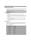
There are two supported wiring standards for 8-conductor (4-pair) RJ-45 terminated UTP cable:
EIA/TIA 568A and B. These standards apply to installations utilizing CAT 5, 5E and 6 cable
specifications. The DSR switching system supports either of these wiring standards.
Table D.1
describes the standards for each pin.
Table D.1: UTP Wiring Standards
Pin EIA/TIA 568A EIA/TIA 568B
1 white/green white/orange
2 green orange
3 white/orange white/green
4 blue blue
5 white/blue white/blue
6 orange green
7 white/brown white/brown
8 brown brown


