


Chapter 3: Installation
Page 3-8 2H22-08R SmartSwitch 2208 User’s Guide
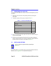
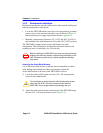
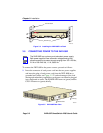
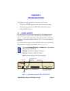
3.6.1 Connecting a Twisted Pair Segment to the
FE-100TX
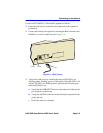
An FE-100TX installed in port slot 7 and/or 8 has an internal crossover
switch. When connecting a workstation, use a straight-through cable and
set the Fast Ethernet Interface Module crossover switch shown in
Figure 3-6 to the straight-through position marked with =. To connect
networking devices, such as another switch, repeater, or router, use a
crossover cable or flip the crossover switch to the crossed over position
marked with an X as shown in Figure 3-6.
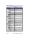
Figure 3-6 FE-100TX Crossover Switch
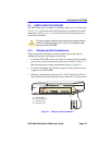
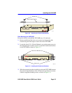
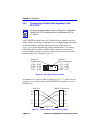
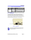
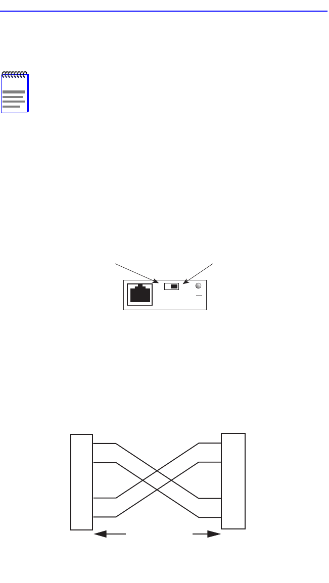
A schematic of a crossover cable is shown in Figure 3-7. If the wires do
not cross over, use the switch on the FE-100TX to internally cross over
the RJ45 port.
Figure 3-7 Cable Pinouts - RJ45 Crossover Cable
NOTE
To ensure proper operation, use only Category 5 Unshielded
Twisted Pair (UTP) cabling that has an impedance of 85 to
111 ohms.
Position X
(crossed over)
1. RX+
2. RX-
3. TX+
4. NC
5. NC
6. TX-
7. NC
8. NC
Position =
(not crossed over)
1. TX+
2. TX-
3. RX+
4. NC
5. NC
6. RX-
7. NC
8. NC
FE-100TX
10
16651_05
100
=
x
TX+
TX–
RX+
RX– 2
1
3
6
10BASE-T Device Port
TX+
TX–
2
1
3
6
RJ45 Port
2251-31
RJ45 to RJ45
RX+
RX–