


Connecting to the Network
2H28-08R SmartSwitch 2208 User’s Guide 3-13
If a link is not established, refer to Chapter 4, Troubleshooting, before
contacting the Cabletron Systems Global Call Center. Refer to
Section 1.6, Getting Help, for details, if the problem has not been
resolved.
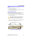
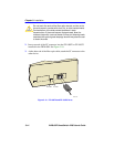
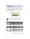
3.5.3 Connecting a Fiber Optic Segment to the
FE-100FX and FE-100F3
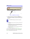
The FE-100FX and FE-100F3 have SC style network ports. See
Figure 3-10. Cabletron Systems offers fiber optic cables that use SC style
connectors. The SC connectors are keyed to ensure proper crossover of
the transmit and receive fibers.
Fiber Optic Network Connection
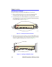
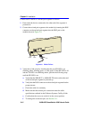
1. Remove the protective rubber covers from the fiber optic ports on the
applicable port on the module and from the ends of the connectors.
Leave the covers on unused ports.
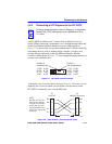
NOTES
An odd number of crossovers (preferably one) must be
maintained between devices so that the transmit port of one
device is connected to the receive port of the other device and
vice versa.
If the fiber optic cable being used has SC style connectors that
do not resemble MIC style connectors, or has SC connectors
on one end and a different type on the other, such as ST
connectors, ensure that the proper crossing over occurs.
Ensure that, when connecting an FE-100F3, single mode cable
is used and the device at the other end of the cable is
compatible for use with single mode fiber.
!
CAUTION
The FE-100F3 uses Class 1 lasers. Do not use optical
instruments to view the laser output. The use of optical
instruments to view laser output increases eye hazard. When
viewing the output optical port, power must be removed from
the network adapter.