


2-11
Cisco 11500 Series Content Services Switch Hardware Installation Guide
78-13884-03
Chapter 2 Cabling the CSS
Cabling the CSS 11503 and CSS 11506 Modules
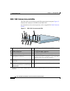
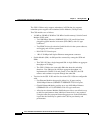
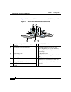
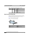
Switch Control Module Connectors and LEDs
The Switch Control Module (SCM), model CSS5-SCM-2GE, provides master
control and is responsible for the following functions:
• System powerup and boot control
• Centralized routing table management
• System-wide connection management
• An interface to an external Network Management Station
• Disk management
• An external RS-232 interface
A CSS supports a maximum of two SCMs, one active and one passive.
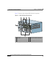
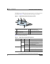
The Switch Control Module contains the following connectors and slots:
• 1 RJ-45 10-Mbps half-duplex Ethernet management connector.
• 1 RJ-45 RS-232 Console connector.
• 1 RJ-45 RS-232 Diag connector (reserved for field service diagnostic use
only).
• 2 SFP GBICs (1000BASE-SX or LX) with LC-type connectors.
• Two PCMCIA slots for a hard disk or flash disk. A cover is preinstalled over
the slots.
Note The SCM can have a maximum of two disk drives.
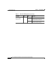
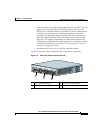
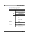
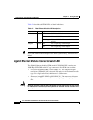
The SCM front panel LEDs indicate module and configuration status:
• Two status module LEDs indicating power and module readiness
• Link/Act and Duplex LEDs for the Ethernet management port
• Link LEDs for each SFP GBIC
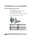
Warning
Because invisible radiation may be emitted from the aperture of the port when
no fiber cable is connected, avoid exposure to radiation and do not stare into
open apertures.