


2-25
Cisco 11500 Series Content Services Switch Hardware Installation Guide
78-13884-03
Chapter 2 Cabling the CSS
Connecting the Chassis to Ground
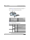
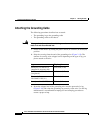
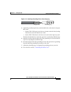
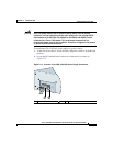
Figure 2-10 Attaching Grounding Wire to Grounding Lug
4.
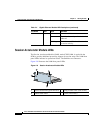
Attach the grounding lug firmly to the threaded holes on the chassis using two
M5 screws.
• On the CSS 11503 chassis, the holes are located on the left side (looking
from the rear) near the bottom rear corner.
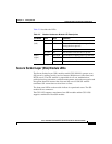
• On the CSS 11506 chassis, the holes are located on the right rear panel.
The three threaded holes are unevenly spaced to accommodate different lugs.
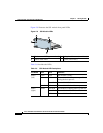
5. Strip the covering from the other end of the grounding wire. See the table in
step 2 for strip lengths for different lugs.
6. Insert the stripped end of the grounding wire into the open end of a grounding
lug and crimp the grounding lug securely to the wire.
7. Attach the grounding lug to an appropriate grounding point at your site.
8. Go to the next section, “Connecting the Power Cord”.
Grounding lugStripped wire
53632