


Chapter 2 Cabling the CSS
Cabling the CSS 11503 and CSS 11506 Modules
2-12
Cisco 11500 Series Content Services Switch Hardware Installation Guide
78-13884-03
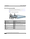
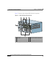
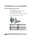
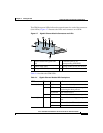
Figure 2-4 illustrates the SCM front panel connectors, PCMCIA slots, and LEDs.
Figure 2-4 Switch Control Module Connectors and LEDs
1 10-Mbps half-duplex Ethernet management
connector
8 RJ-45 RS-232 Console connector
2 Bicolor status LED (green and red) 9 RJ-45 RS-232 Diag connector for field
service diagnostic use only. (A connector
cover is provided. Removing the cover voids
the warranty.)
3 Amber status LED 10 PCMCIA slot cover
4 Link/Act LED 11a PCMCIA slot 0 containing a flash or hard
disk
5 Duplex LED 11b PCMCIA slot 1 (shown empty) for optional
installation of a second flash or hard disk
6 LC-type SFP GBIC (one of two) 12 Recessed button (reserved for field service
use only)
7 Link LED for the associated SFP GBIC on
the left
78993
C
S
S
5-S
C
M
-2G
E
S
ystem
C
on
trol
D
U
P
L
E
X
L
IN
K
/A
C
T
MANAGEMENT
10BASE-T
S
L
O
T
0
S
L
O
T
1
G
E
1
G
E
2
L
IN
K
L
IN
K
S
T
A
T
U
S
P
C
M
C
IA
C
O
N
S
O
L
E
2
1
9
8
3
4
5
6
11b
7
10 11a12