


Chapter 2 Cabling the CSS
Connecting the Chassis to Ground
2-24
Cisco 11500 Series Content Services Switch Hardware Installation Guide
78-13884-03
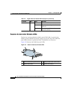
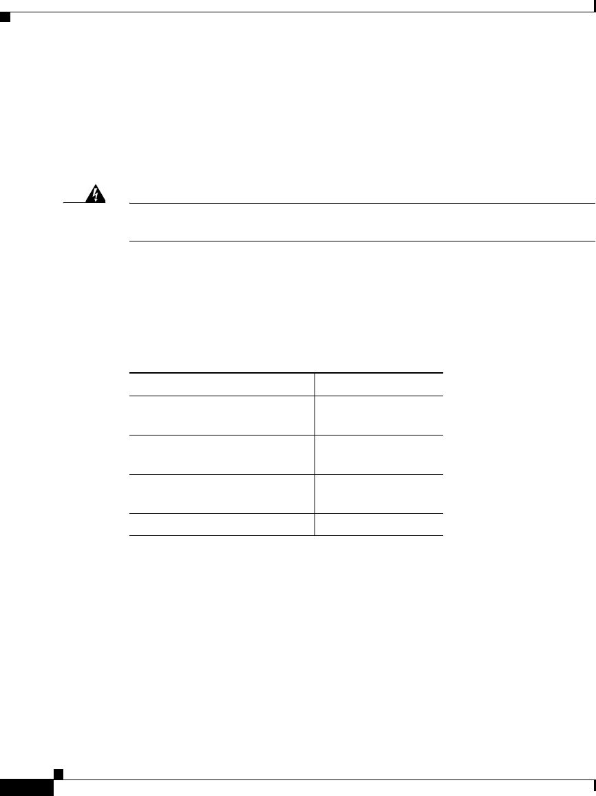
Attaching the Grounding Cable
The following procedure describes how to attach:
• The grounding lug to the grounding cable
• The grounding cable to the chassis
Warning
When you install or replace the unit, the ground connection must always be
made first and disconnected last.
1. Power off the chassis by setting the power switch (or switches) to the O (off)
position.
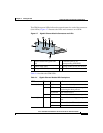
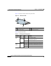
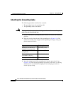
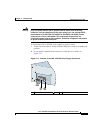
2. Strip the covering from the end of the grounding wire (Figure 2-10). The
amount of covering to be stripped varies depending on the type of lug you
plan to attach to the wire.
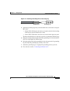
3. Insert the stripped end of the grounding wire into the open end of a lug
(Figure 2-10) and crimp the grounding lug securely to the wire. Use the lug
manufacturer’s recommended crimping tool and crimping procedure to
ensure a proper crimp.
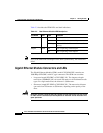
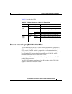
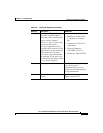
Lug Strip Length
Panduit no. LCD6-10A-L
(supplied in accessory kit)
13/16 inch (2 cm)
Panduit no. LCC6-10A-L
(long barrel)
1 1/16 inch (2.7 cm)
Thomas & Betts no.
256-30695-1183(*4*)
3/4 inch (1.9 cm)
Burndy no. YA6CL2TC10 7/8 inch (2.2 cm)