


Chapter 2 Cabling the CSS
Connecting the Power Cord
2-34
Cisco 11500 Series Content Services Switch Hardware Installation Guide
78-13884-03
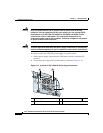
Warning
Only a DC power source that is isolated from AC mains with reinforced
insulation, and that complies with the other safety extra-low voltage (SELV)
requirements in UL1950, CSA 950 3rd Edition, EN 60950, and IEC950, can be
connected to a Cisco 11506 system. This requirement ensures that in a
catastrophic power source fault condition, hazardous voltages are not present
on power terminals and connectors.
Warning
This unit might have more than one power supply connection; all connections
must be removed completely for you to completely remove power from the unit.
To connect each CSS 11506 DC power supply to a power source:
1. On the power supply, ensure that the CSS power switch is in the O (off)
position.
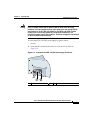
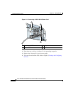
2. Locate the power supply DC terminal block, as shown in Figure 2-15.
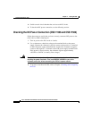
Figure 2-15 Location of CSS 11506 DC Power Supply Connectors
1 Power supply LEDs 3 Terminal block (–, +, and )
2 Power switch
C
S
S
5
-1
0
M
-2
G
E
G
ig
a
b
it E
th
e
rn
e
t
G
E
1
G
E
2
L
IN
K
L
IN
K
1
2
3
C
S
S
5
-1
0
M
-1
6
F
E
1
2
3
4
5
6
P
S1
PS2
P
S3
7
D
ISC
O
N
N
ECT A
LL
PO
W
E
R
SO
U
RC
ES
B
EFO
R
E SERVIC
IN
G
C
A
U
TIO
N
8
100-240V
~
5A 50-60 Hz
AC
O
K
DC
O
K
-48/-60V
10/8A
I/P
OK
DC
OK
A
C
O
K
D
C
O
K
59546
3
1 2
59199