


2-35
Cisco 11500 Series Content Services Switch Hardware Installation Guide
78-13884-03
Chapter 2 Cabling the CSS
Connecting the Power Cord
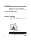
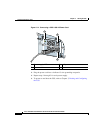
3. Using a flat-head screwdriver, loosen the captive screws on the three DC
connectors (labeled from left to right, –, +, and , respectively).
Warning
Before installing a wire, ensure that the polarity of the DC connections is
correct. Reversed polarity can cause damage to the DC power supply and can
create a dangerous shock hazard.
Do not consolidate the end of a conductor by soft soldering prior to installation.
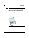
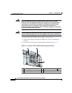
4. Install the wires into the appropriate connector. Make sure that the
non-insulated part of each wire is 9 mm (0.35 inches) in length.
Warning
When installing the wires, always connect the ground wire first. When
disconnecting the wires, always disconnect the ground wire last.
5. Tighten the captive screws to 5 to 7 inch-pounds (0.6 to 0.8 Nm) of torque to
secure the wires in the connectors. Ensure that the wires are held firmly in
place.
6. Repeat steps 1 through 5 for each power supply.
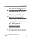
7. Install the three sets of wires to the DC power source.
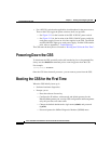
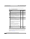
For the proper power cable wiring between the CSS 11506 and DC power
source, see Table 2-10.
Warning
The proper wiring sequence is ground to ground, positive to positive, and
negative to negative. The ground wire should always be connected first and
disconnected last.
9199
Table 2-10 CSS 11506 to DC Power Source Cabling
CSS 11506 DC Power Source
(Ground)
(Ground)
++
––