


2-17
Cisco 11500 Series Content Services Switch Hardware Installation Guide
78-13884-03
Chapter 2 Cabling the CSS
Cabling the CSS 11503 and CSS 11506 Modules
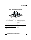
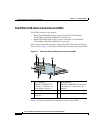
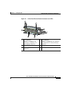
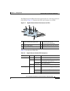
The GEM front panel LEDs indicate the network status for each of the connectors
(Link LEDs). Figure 2-7 illustrates the LEDs and connectors on a GEM.
Figure 2-7 Gigabit Ethernet Module Connectors and LEDs
Table 2-4 describes the GEM LEDs.
1 Bicolor status LED (green and
red)
4 Link LED (next to its
corresponding SFP GBIC)
2 Amber status LED 5 Spring-loaded screw (one of two)
3 LC-type SFP GBIC (one of two) 6 Ejector (one of two)
59535
C
S
S
5
-1
0
M
-2
G
E
2
G
ig
a
b
it E
th
e
r
n
e
t
G
E
1
G
E
2
L
IN
K
L
IN
K
S
T
A
T
U
S
1
2
3
4
4
5
6
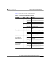
Table 2-4 Gigabit Ethernet Module LED Descriptions
LED Name Color State Indicates
Status (left) Green Solid The module is ready.
Red Solid The module failed the power-up self
test during the boot process.
Slow blink The module failed.
No color Off The module failed and has no power.
Status (right) Amber Fast blink The module is running power-up self
test.
Slow blink The module is offline and active.
Solid The module is online and not active.