


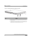
Chapter 3 Installing the GSS
Installing Your GSS
3-8
Cisco Global Site Selector 4491 Hardware Installation Guide
78-16356-01
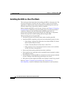
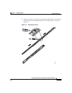
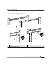
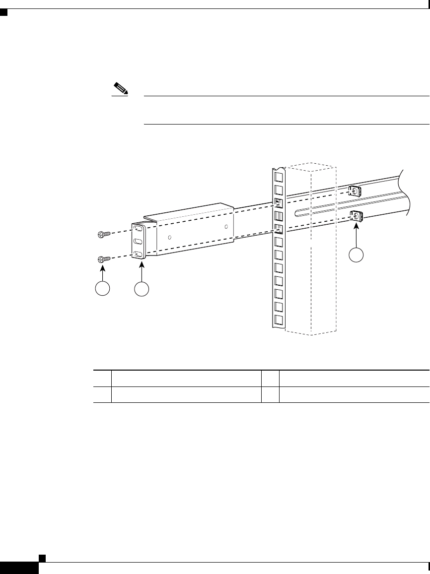
4. Select a location in the rack to mount the GSS and attach the front end of the
right outer telescopic rail to the right side of the rack, as show in Figure 3-4.
Note Racks that contain tapped mounting holes do not require the cage
nuts (3) shown in Figure 3-4.
Figure 3-4 Attaching Front Rail to the Right Side of the Rack
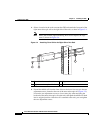
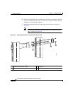
5. Extend the middle rail from the front of the rack to have free access to the two
adjustment screws located at the rear of the outer telescopic rail (Figure 3-5).
Loosen the two adjustment screws to leave some play when attaching the
back end of the outer telescopic rail to the rack, then push the middle rail back
into its original position. After the rail is attached to the rack, you can tighten
the two adjustment screws.
119962
3
1
2
1 Round head screw and washer 3 Cage nut
2 Right outer telescopic rail—front