


Chapter 1. Product Overview
EK–SMCPQ–UG. C01 1–9
•
Two-speed blower operation
•
SBB shelf blower control to include error detection, reporting, and automatic
corrective action
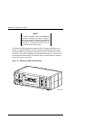
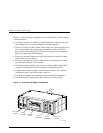
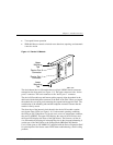
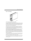
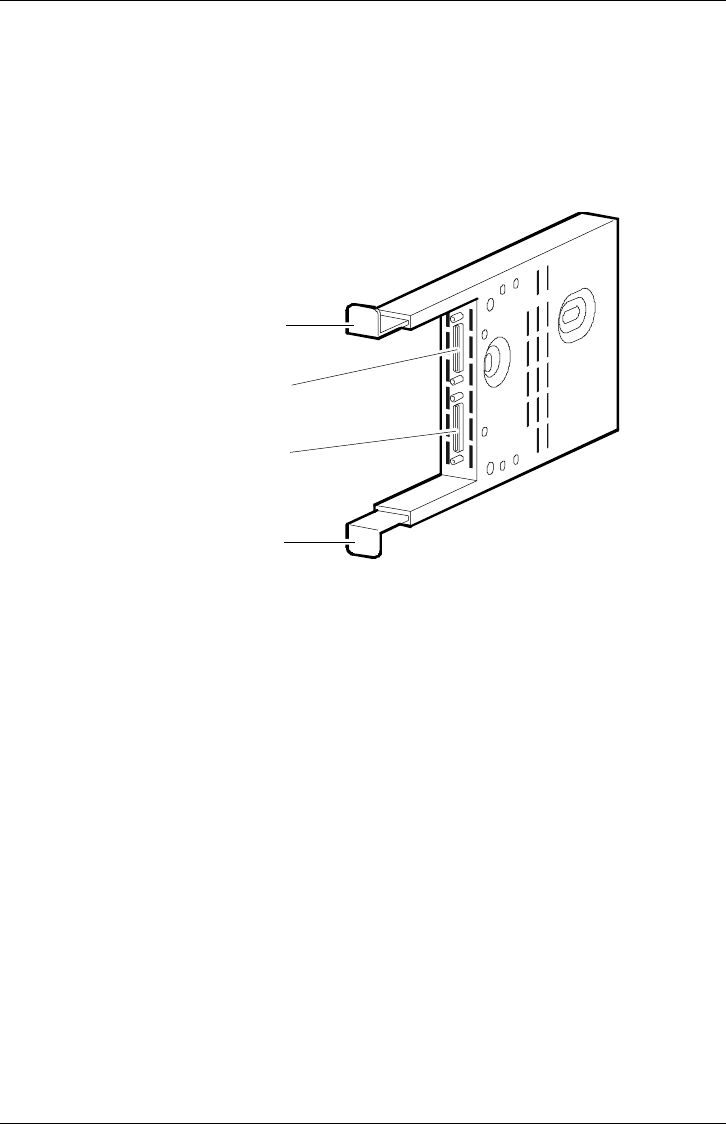
Figure 1–5 Device I/O Module
S
HR-1
0
4
5
Upper
Mounting
Tab
Lower
Mounting
Tab
Device Port 0
Connector
Device Port 1
Connector
The dual-channel device I/O module has two 68-pin VHDCI female connectors
mounted on the front panel (see Figure 1–5). The upper connector is the “device
port 0” connector. The lower connector is the “device port 1” connector.
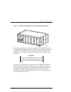
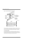
The device I/O module top and bottom guides properly align the module in the
shelf and with the backplane connector at the back of the shelf. When you install
the module the two-spring steel mounting tabs expand and engage the shelf. The
combination of the mounting tabs and the backplane connector ensures that the
module is firmly seated.
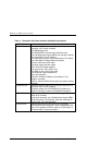
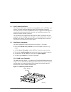
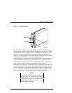
The front edge of the internal circuit board in the device I/O module contains
two-blower status LEDs (see Figure 1–6). Under normal operating conditions,
the LEDs are ON. When there is a blower error or an over-temperature condition,
they are FLASHING. The upper LED displays the status of the left blower and
the lower LED displays the status of the right blower. The blowers cool the de-
vice I/O module by drawing air in through the slots in the front and exhausting it
out the rear of the shelf. Refer to the StorageWorks SBB Shelf I/O Module
User’s Guide (part no. EK-SBBIO-UG) supplied with the Device Expansion Shelf
for a description of the blower status LEDs when troubleshooting a shelf-cooling
problem.