


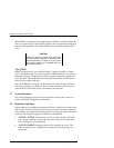

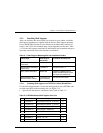

RAID Array 3000 Controller Shelf
3–2 EK–SMCPQ–UG. C01
•
Install the UPS below the shelves and as low as possible in the cabinet.
•
Ensure there is a approximate two-inch gap between the bottom of the con-
troller shelf and the UPS to allow cable routing between the front panel con-
nectors and connectors at the back of the units.
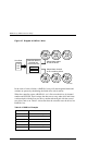
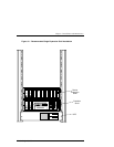
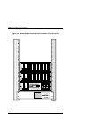
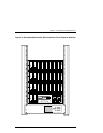
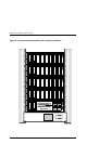
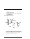
3.2 Installing Shelves in the Cabinet
Determining the best location to install the Controller and Device Expansion
Shelves in the cabinet depends on the number of expansion shelves in your sub-
system configuration. The shelves should be grouped as shown Figures 3–1
through 3–4. Figure 3–1 shows a single Device Expansion Shelf installation.
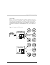
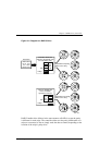
Figures 3–2, 3–3, and 3–4 show a two, three, and four shelf installation, respec-
tively.
Install the UPS at the bottom of the cabinet with the subsystem shelves directly
above. The host system (not shown) can reside between the UPS and the subsys-
tem shelf group.
Note that the Controller Shelf in each figure is located directly below the first
Device Expansion Shelf. This minimizes the distance between the connectors to
enable the 0.5 meter SCSI cable connections between the modules in the Con-
troller Shelf and each Device Expansion Shelf.
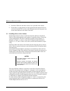
NOTES
• The distance between shelves should not ex-
ceed one 1.5 inches.
• Because of power cord lengths, the distance
between the last Device Expansion Shelf at the
top of a shelf group and the UPS should not ex-
ceed 45 inches.
The target SCSI bus addresses of the drives in the Device Expansion Shelves
(shown on each storage device in Figures 3–1 through 3–4) are controlled by a
switch on the side of the personality I/O module in each expansion shelf. In a
single expansion shelf configuration, the IDs are 0–5. In a double expansion shelf
configuration, the IDs in both expansion shelves are also 0–5 because each shelf
is connected to a separate device I/O bus from the controller.
In a three and four-shelf configuration (Figures 3–3 and 3–4, respectively), the
second expansion shelf on each device I/O bus is connected to the first via a
Trilink adapter and must be set to 8–13.