


RAID Array 3000 Controller Shelf
2–12 EK–SMCPQ–UG. C01
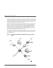
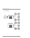
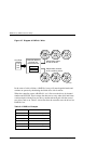
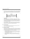
Figure 2–7 Diagram of RAID 0+1 Write
1110
1101
1011
Host Data
Controller divides
the data into
chunksized units
1110
1101
1011
Striped data written
to half the drives
Striped data mirrored
to the remaining drives
S
HR-1
0
5
6
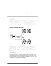
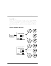
In the event of a drive failure, a RAID 0+1 array will enter degraded mode and
continue to operate by substituting the failed drive with its mirror.
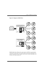
When the controller creates a RAID 0+1 set, it first sorts the drives by channel
number and SCSI ID. Then it stripes the data across every other drive and forms
a mirrored pair with the first two drives, another mirrored pair with the second
two drives, and so on. Table 2–4 describes how the controller uses the drives in a
RAID 0+1 set.
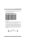
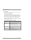
Table 2–4 RAID 0+1 Example
Drives Selected Function
Channel 1, ID 0 First member of stripe set.
Channel 1, ID 1 Mirror of channel 1, ID 0
Channel 1, ID 2 Second member of stripe set
Channel 2, ID 0 Mirror of channel 1, ID 2
Channel 2, ID 1 Third member of stripe set
Channel 2, ID 2 Mirror of channel 2, ID 1