


RAID Array 3000 Controller Shelf
3–18 EK–SMCPQ–UG. C01
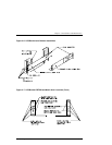
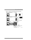
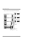
3.3.3 Cabling a Two Device Expansion Shelf Subsystem
(See Figures 3–10 and 3–11)
1.
Ensure the physical installation phase of installing and securing shelf brack-
ets and shelves (including the UPS) has been accomplished and that the
shelves are secured within the shelf bracket the shelf lock provided.
2.
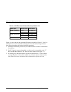
Remove the device I/O module from the Controller Shelf and ensure the
switch positions of SCSI bus termination switch S4 are set as shown in Fig-
ure 3–9. Replace the module in the Controller Shelf.
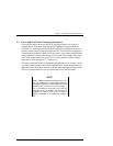
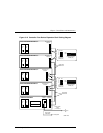
3.
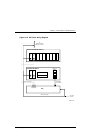
Remove the personality I/O module from Device Expansion Shelf # 1 and
set SCSI bus termination switch S4 and SCSI bus address switch S3 on this
module as shown in Figure 3–11.
4.
Remove the personality I/O module from Device Expansion Shelf # 2 and
repeat step 3.
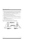
5.
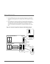
Connect the black ac power cords (supplied with the shelves) from the ac
power source to the outside power supply on each shelf (see Figure 3–10).
6.
Connect the gray power cables from the inside power supply on each shelf to
the power receptacles on the back of the UPS (ensure the UPS is connected
to an ac source.
7.
Connect a 0.5-meter SCSI cable (BN37A-0E) from the top SCSI connector
on the Controller Shelf device I/O module (device bus 1) and the SCSI con-
nector on the front of the personality I/O module on the Expansion Shelf.
8.
Connect a second 0.5-meter SCSI cable (BN37A-0E) from the bottom SCSI
connector on the Controller Shelf device I/O module (device bus 2) and the
SCSI connector on the front of the personality I/O module on the Device
Expansion Shelf # 2.
9.
Connect a 5-meter SCSI cable (BN37A-05) between the host-in connector
on the Controller Shelf host 0 I/O module (bottom connector) and the corre-
sponding connector on the host system.
10.
Connect the maintenance serial control cable (17-04730-01) from the CTR 0
connector on the Controller Shelf host 0 I/O module to the corresponding
connector on the maintenance PC.
11.
Connect the UPS serial control cable (17-04729-01) from the UPS connector
Controller Shelf host 0 I/O module to the like connector on the UPS.
12.
Install jumper connector 12-49700-01 to the Controller Shelf UPS connector
on the host 1 I/O module.