


Chapter 2. RAID Array Controller
EK–SMCPQ–UG. C01 2–5
•
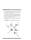
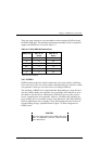
Stripesets (RAID 0) combine disk drives in serial to increase transfer or re-
quests rates
•
Mirrorsets (RAID 1) combine disk drives in parallel to provide a highly reli-
able storage unit
•
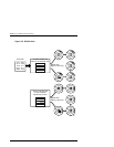
RAID 4 provides striping with a fixed parity drive
•
RAIDsets (RAID 5) combine disk drives in serial - just like stripesets - but
also store parity data to ensure high reliability
•
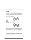
Stripe mirrorsets (RAID 0 + 1) combine mirrorsets in serial to provide the
highest throughput and availability of any storage unit
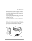
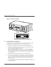
2.3 Controller Reset and LED Indicators
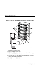
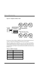
Figure 2–4 illustrates the front panel of the controller. All LEDs are numbered
from left to right. The reset button (LED 0) flashes green about once every sec-
ond (heartbeat) to indicate that the controller is operating normally. LEDs 1
through 4-display host and disk channel activity (amber). LED 5 (normally off)
comes on red during a controller failure. The LED/Reset switch interface is de-
fined in Table 2–1.
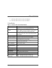
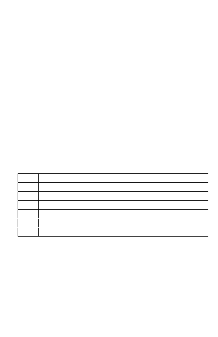
Table 2–1 LED/Reset Switch Interface
LED # Name
0 Heart Beat/LED Controller Reset Switch (green)
1 Host Channel 0 Activity LED (amber)
2 Host Channel 1 Activity LED (amber)
3 Disk Channel 0 Activity LED (amber)
4 Disk Channel 1 Activity LED (amber)
5 Fault LED (red)