


Technical Reference Guide
Compaq iPAQ Family of Internet Devices
First Edition - March 2000
5-25
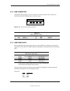
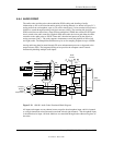
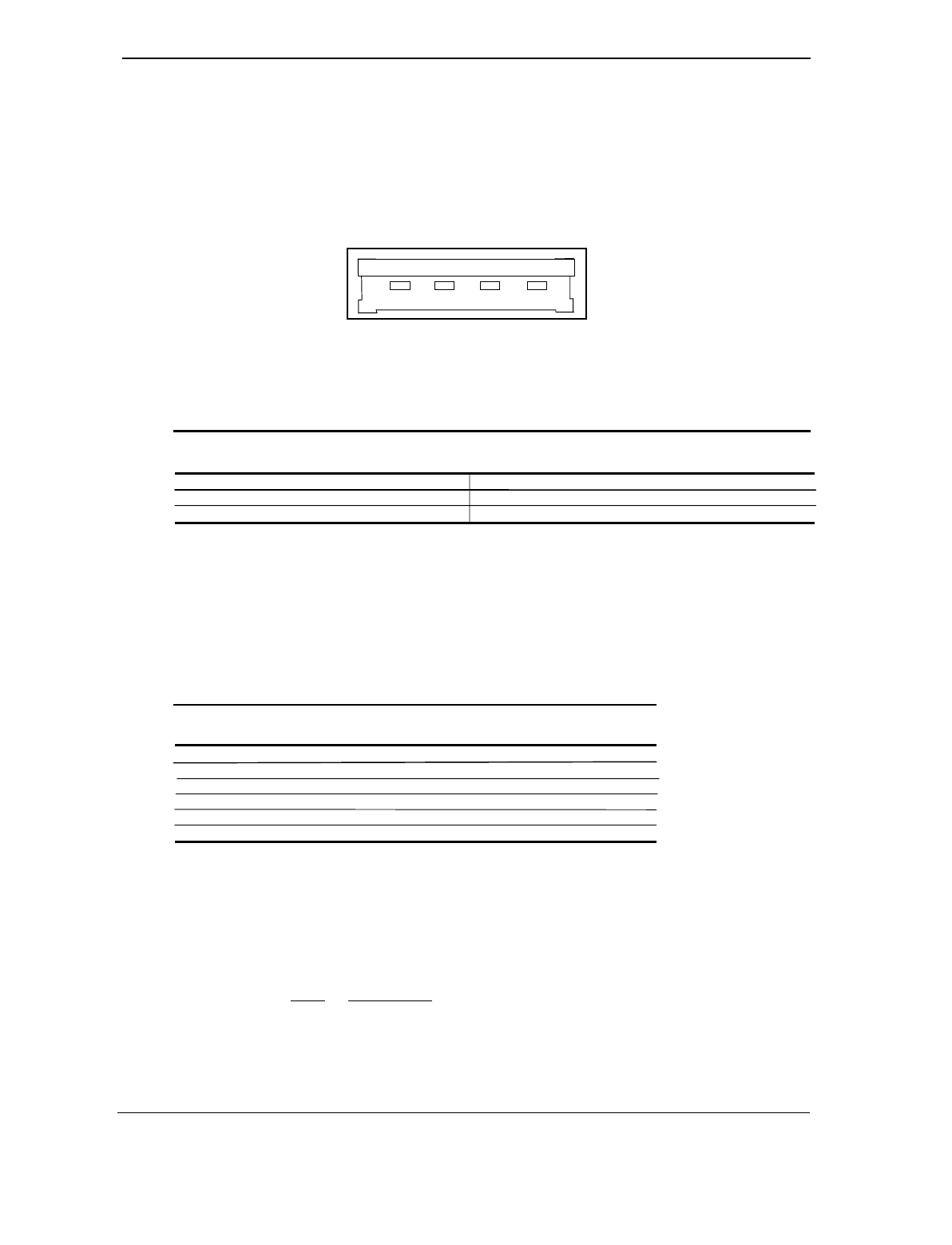
5.7.3 USB CONNECTOR
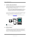
The USB interface provides two series-A connectors on the front panel and, on legacy-free
models, three series-A USB connectors on the rear panel.
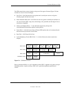
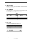
Figure 5-10.
Universal Serial Bus Connector
Table 5–17. USB Connector Pinout
Table 5-17.
USB Connector Pinout
Pin Signal Description Pin Signal Description
1 Vcc +5 VDC 3 USB+ Data (plus)
2 USB- Data (minus) 4 GND Ground
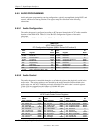
5.7.4 USB CABLE DATA
The recommended cable length between the host and the USB device should be no longer than
sixteen feet for full-channel (12 MB/s) operation, depending on cable specification (see following
table).
Table 5–18. USB Cable Length Data
Table 5-18.
USB Cable Length Data
Conductor Size Resistance Maximum Length
20 AWG 0.036
Ω
16.4 ft (5.00 m)
22 AWG 0.057
Ω
9.94 ft (3.03 m)
24 AWG 0.091
Ω
6.82 ft (2.08 m)
26 AWG 0.145
Ω
4.30 ft (1.31 m)
28 AWG 0.232
Ω
2.66 ft (0.81 m)
NOTE:
For sub-channel (1.5 MB/s) operation and/or when using sub-standard cable
shorter lengths may be allowable and/or necessary.
The shield, chassis ground, and power ground should be tied together at the host end but left
unconnected at the device end to avoid ground loops.
Color code:
Signal Insulation color
Data + Green
Data - White
Vcc Red
Ground Black
1
2
3
4