


Technical Reference Guide
Compaq iPAQ Family of Internet Devices
First Edition - March 2000
5-11
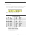
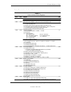
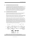
5.5.4.2 Parallel Interface Control
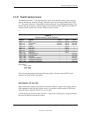
The BIOS function INT 17 provides simplified control of the parallel interface. Basic functions
such as initialization, character printing, and printer status are provide by subfunctions of INT
17. The parallel interface is controllable by software through a set of I/O mapped registers. The
number and type of registers available depends on the mode used (SPP, EPP, or ECP). Table 5-9
lists the parallel registers and associated functions based on mode.
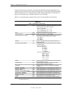
Table 5–9.
Parallel Interface Control Registers
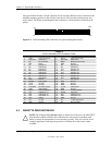
Table 5-9.
Parallel Interface Control Registers
I/O
Address Register
SPP Mode
Ports
EPP Mode
Ports
ECP Mode
Ports
Base Data LPT1,2,3 LPT1,2 LPT1,2,3
Base + 1h Printer Status LPT1,2,3 LPT1,2 LPT1,2,3
Base + 2h Control LPT1,2,3 LPT1,2 LPT1,2,3
Base + 3h Address -- LPT1,2 --
Base + 4h Data Port 0 -- LPT1,2 --
Base + 5h Data Port 1 -- LPT1,2 --
Base + 6h Data Port 2 -- LPT1,2 --
Base + 7h Data Port 3 -- LPT1,2 --
Base + 400h Parallel Data FIFO -- -- LPT1,2,3
Base + 400h ECP Data FIFO -- -- LPT1,2,3
Base + 400h Test FIFO -- -- LPT1,2,3
Base + 400h Configuration Register A -- -- LPT1,2,3
Base + 401h Configuration Register B -- -- LPT1,2,3
Base + 402h Extended Control Register -- -- LPT1,2,3
Base Address:
LPT1 = 378h
LPT2 = 278h
LPT3 = 3BCh
The following paragraphs describe the individual registers. Note that only the LPT1-based
addresses are given in these descriptions.
Data Register, I/O Port 378h
Data written to this register is presented to the data lines D0-D7. A read of this register when in
SPP-compatible mode yields the last byte written. A read while in SPP-extended or ECP mode
yields the status of data lines D0-D7 (i.e., receive data).
In ECP mode in the forward (output) direction, a write to this location places a tagged command
byte into the FIFO and reads have no effect.