


Chapter 7 Power and Signal Distribution
Compaq iPAQ Family of Internet Devices
First Edition - March 2000
7-4
7.3 POWER DISTRIBUTION
7.3.1 3.3/5/12 VDC DISTRIBUTION
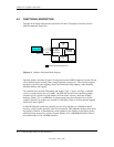
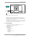
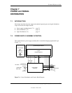
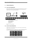
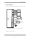
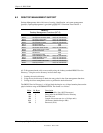
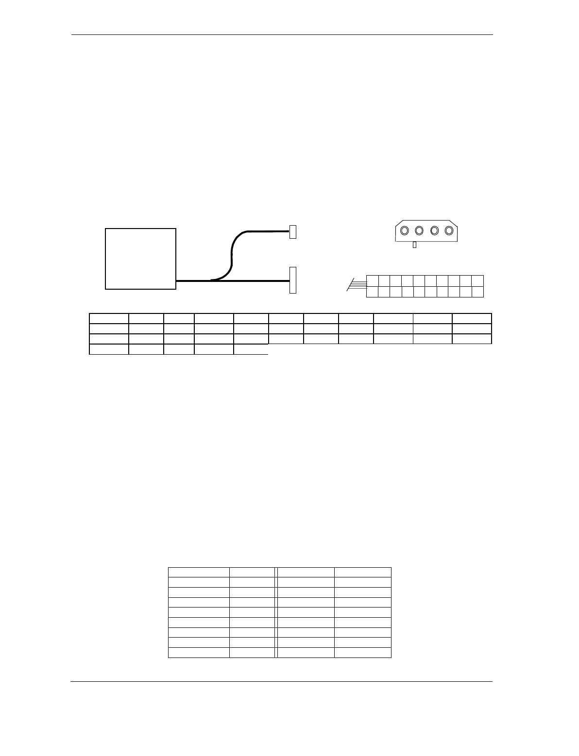
The power supply assembly includes a multi-connector cable assembly that routes +3.3 VDC, +5
VDC, -5 VDC, +12 VC, and -12 VDC to the system board as well as to the individual drive
assemblies. Figure 7-2 shows the power supply cabling.
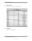
Conn. # Pin 1 Pin 2 Pin 3 Pin 4 Pin 5 Pin 6 Pin 7 Pin 8 Pin 9 Pin 10
P1 +3.3 +3.3 RTN +5 RTN +5 RTN PwrGd +5 Aux +12
P1 [1] +3.3 -12 RTN PS On RTN RTN RTN FO +5 +5
P3 +5 GND GND +12
NOTES:
[1] This row represents pins 11-20 of connector P1.
All + and - values are VDC
.
RTN = Return (signal ground)
GND = Power ground
PwrGd = Power Good
FO = Fan off
Figure 7–2
. Power Cable Diagram
7.3.2 LOW VOLTAGE DISTRIBUTION
Voltages less than 3.3 VDC (including processor core (VccP) voltage) are produced through
regulator circuitry on the system board.
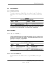
An on-board regulator produces the VccP (processor core) voltage according to the strapping of
signals VID3..0 by the processor. The possible voltages available are listed as follows:
VID 3..0 VccP VID 3..0 VccP
0000 2.05 VDC 1000 1.65 VDC
0001 2.00 VDC 1001 1.60 VDC
0010 1.95 VDC 1010 1.55 VDC
0011 1.90 VDC 1011 1.50 VDC
0100 1.85 VDC 1100 1.45 VDC
0101 1.80 VDC 1101 1.40 VDC
0110 1.75 VDC 1110 1.35 VDC
0111 1.70 VDC 1111 1.30 VDC
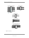
P1
1 2 5 43 7 6
12
10
11
8 9
13 14 15 16 17 18 19 20
Power Supply
Assembly
(SP# 159447)
P1
P3
1 2 3 4
P3